17
DBR10/DBR12/DBR15
C-2. Shield AMP Assembly
(Time required: About 1 minute)
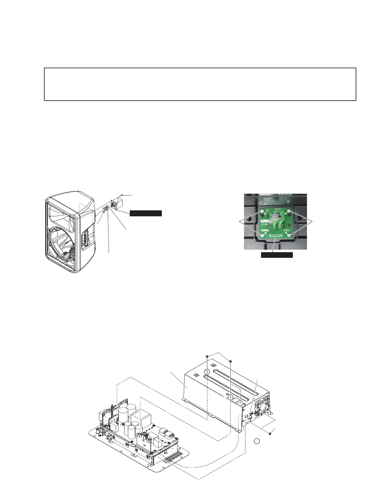
C-2-1 Remove the connector assembly of DC fan. (Fig. C-2)
C-2-2 Remove the fi ve (5) screws marked [380]. The shield
AMP assembly can then be removed. (Fig. C-2)
*
When installing the shield AMP assembly, fi rst tighten
the three (3) priority screws in order as shown in Fig.
C-2.
C. Disassembly of Amp Assembly
C-1. SUBL (SP IN) Circuit Board
(Time required: About 8 minutes)
C-1-1 Remove the grille assembly. (See procedure A-1, B-1.)
C-1-2
Remove the loud speaker (woofer).
(See procedure A-2, B-2.)
C-1-3 Remove the amp assembly. (See procedure A-5, B-5.)
C-1-4 Remove the HF/LF connector assembly from the SUBL
(SP IN) circuit board.(Fig. C-1)
C-1-5 Remove the four (4) screws marked [40] (DBR10) or
marked [50] (DBR12/DBR15). The SUBL (SP IN)
circuit board can then be removed. (Fig. C-1, Photo C-1)
'%5 >@
'%5'%5>@
SUBL
(
SP IN
)
/)&211(&725
$66(0%/<5('%/$&.
(WC 組立 LF12 束線(赤/黒))
+)&211(&725
$66(0%/<<(//2:%/8(
(WC 組立 HF12 束線(黄/青))
>@
>@
6+,(/'$03$66(0%/<
(シールド AMP 組立)
&211(&725$66(0%/<
RI'&)$1
(DC ファンの束線)
e
w
q
35,25,7<6&5(:
(優先ネジ)
C-2. シールドAMP組立
(所要時間:約1分)
C-2-1 DCファンの束線を外します。(図C-2)
C-2-2 [380]のネジ5本を外して、シールドAMP組立を外
します。(図C-2)
※ シールドAMP組立を取り付け時には、優先ネジ3本を図
に示す順番で先に締めてください。(図C-2)
※
This fi gure shows the DBR12.
(この図は、DBR12です。)
Fig. C-1
(図C-1)
Fig. C-2
(図C-2)
C. アンプ組立の分解
C-1. SUBL(SPIN)シート
(所要時間:約8分)
C-1-1 グリル組立を外します。(A-1、B-1項参照)
C-1-2 スピーカ(ウーファー)を外します。
(A-2、B-2項参照)
C-1-3 アンプ組立を外します。(A-5、B-5項参照)
C-1-4 WC組立HF/LF束線をSUBL(SPIN)シートから外
します。(図C-1)
C-1-5 [40](DBR10)または、[50](DBR12/DBR15)のネジ
4本を外して、SUBL(SPIN)シートを外します。
(図C-1、写真C-1)
'%5 >@
'%5'%5>@
'%5 >@
'%5'%5>@
SUBL
(
SP IN
)
Photo C-1
(写真C-1)
※ 分解の前に、あらかじめアンプ組立を外しておきます。
(A-5 項、B-5 項参照)
※ インシュロックタイなどを外したときは必ず外す前と
同じように取付けてください。
* Before disassembly, remove the amp assembly in
advance. (See procedure A-5, B-5.)
* When you remove binding ties and such, always
install as before removal.
 Loading...