Contents [ hide
1 ELECTRONIC DRUM KIT
2 DTX6K-X
2.1 Assembly Manual
3 Safety Precautions
3.1 1 Open the boxes to reveal their contents.
3.2 Components of DTX6K-X
3.3 2 Assemble the electronic drum rack.
3.4 3 Assemble the hi-hat holder, the pads and the drum trigger module to the electronic
drum rack.
3.5 Assembling the hi-hat holder
3.6 Assembling the snare and tom pads
3.7 Assembling the drum trigger module, cymbal pads, and hi-hat pad
3.8 Assembling the kick pad
3.9 4 Arrange the hi-hat controller and the kick pad as shown in Example of standard
assembly on the other side of this sheet.
4 5 Connect the pads to the drum trigger module.
5 6 Connect the drum trigger module to a power supply.
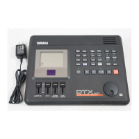
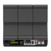
6 7 Setting up the drum trigger module.
7 Related Manuals:
ELECTRONIC DRUM KIT
DTX6K-X
Assembly Manual
Manual Development Group
© 2020 Yamaha Corporation
Published 04/2020
POMA*.*- **A0
VCR2740
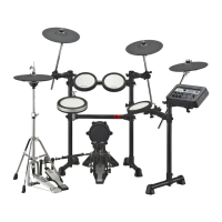
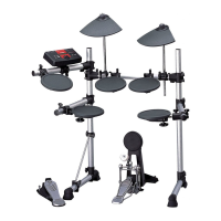
Thank you for purchasing the Yamaha ELECTRONIC DRUM KIT DTX6K-X. This electronic drum kit
can be used in your home or a studio, or onstage for live performances. For proper assembly and
safe use, please read this assembly manual carefully before using it. After you have read the
manual, keep it in a safe and handy place for future reference. This manual describes the
standard assembly procedure for the DTX6K-X electronic drum kit. It covers assembly, wiring and
setting up the drum trigger module of the kit as shown below.
Example of standard assembly