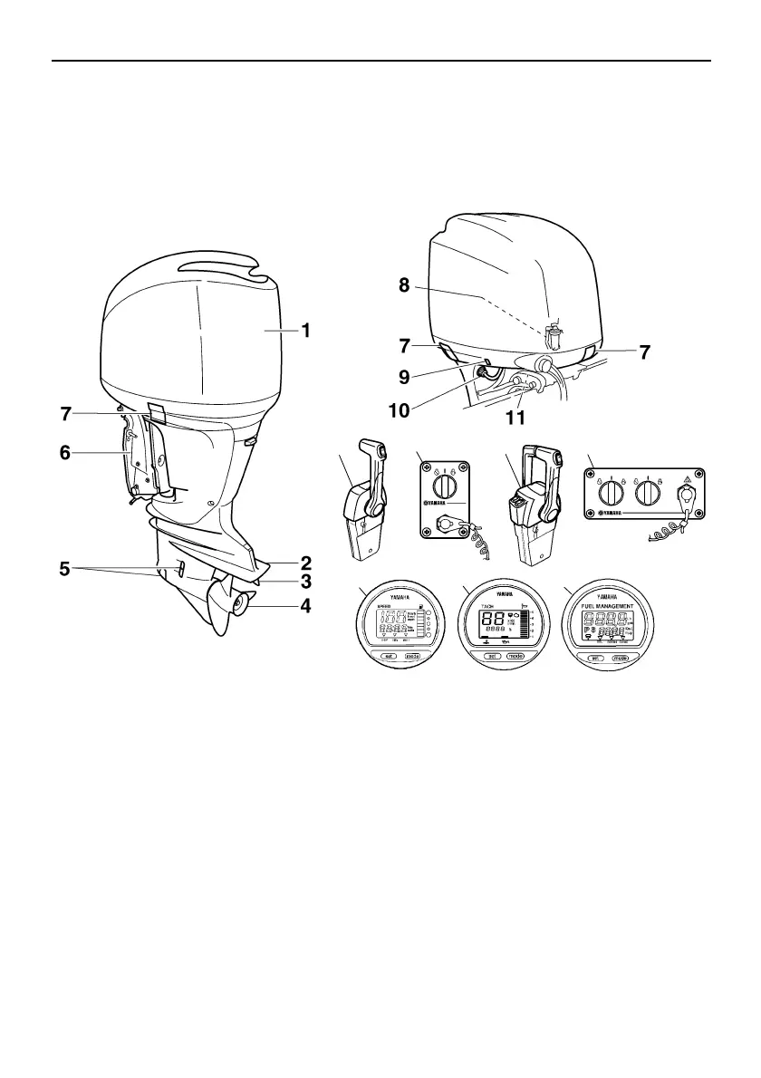
Components
16
EMU2579Y
Components diagram
IP:
* May not be exactly as shown; also may not be included as standard equipment on all models
(order from dealer).
F200C, FL200C, F225B, FL225B, F225C, F250A, FL250A
ZMU05148
12 13 14 15
16 17 18
1. Top cowling
2. Anti-cavitation plate
3. Trim tab (anode)
4. Propeller*
5. Cooling water inlet*
6. Clamp bracket
7. Cowling lock lever(s)
8. Water separator
9. Power trim and tilt switch
10.Flushing device
11.Tilt support lever
12.Remote control box (binnacle mount type)*
13.Switch panel (for use with binnacle type)*
14.Remote control box (binnacle mount type)*
15.Switch panel (for use with binnacle type)*
16.Digital speedometer*
17.Digital tachometer*
18.Fuel management meter*
U6P278E0.book Page 16 Monday, April 11, 2011 7:37 PM