AIR INDUCTION SYSTEM
7-18
EAS27060
CHECKING THE AIR INDUCTION SYSTEM
Air injection
The air induction system burns unburned ex-
haust gases by injecting fresh air (secondary air)
into the exhaust port, reducing the emission of
hydrocarbons. When there is negative pressure
at the exhaust port, the reed valve opens, allow-
ing secondary air to flow into the exhaust port.
The required temperature for burning the un-
burned exhaust gases is approximately 600 to
700 C (1112 to 1292 F).
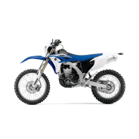
Air cut-off valve
The air cut-off valve is controlled by the signals
from the ECU in accordance with the combus-
tion conditions. Ordinarily, the air cut-off valve
opens to allow the air to flow during idle and
closes to cut-off the flow when the vehicle is be-
ing driven. However, if the coolant temperature
is below the specified value, the air cut-off valve
remains open and allows the air to flow into the
exhaust pipe until the temperature becomes
higher than the specified value.
1. Check:
• Hoses
Loose connections Connect properly.
Cracks/damage Replace.
2. Check:
• Reed valve
• Reed valve stopper
• Reed valve seat
Cracks/damage Replace the reed valve
assembly.
3. Measure:
• Reed valve bending limit “a”
Out of specification Replace the reed
valve assembly.
4. Check:
• Air cut-off valve
Cracks/damage Replace.
5. Check
• Air induction system solenoid
Refer to “CHECKING THE AIR INDUCTION
SYSTEM SOLENOID” on page 8-108.
EAS1RC1712
INSTALLING THE AIR INDUCTION SYSTEM
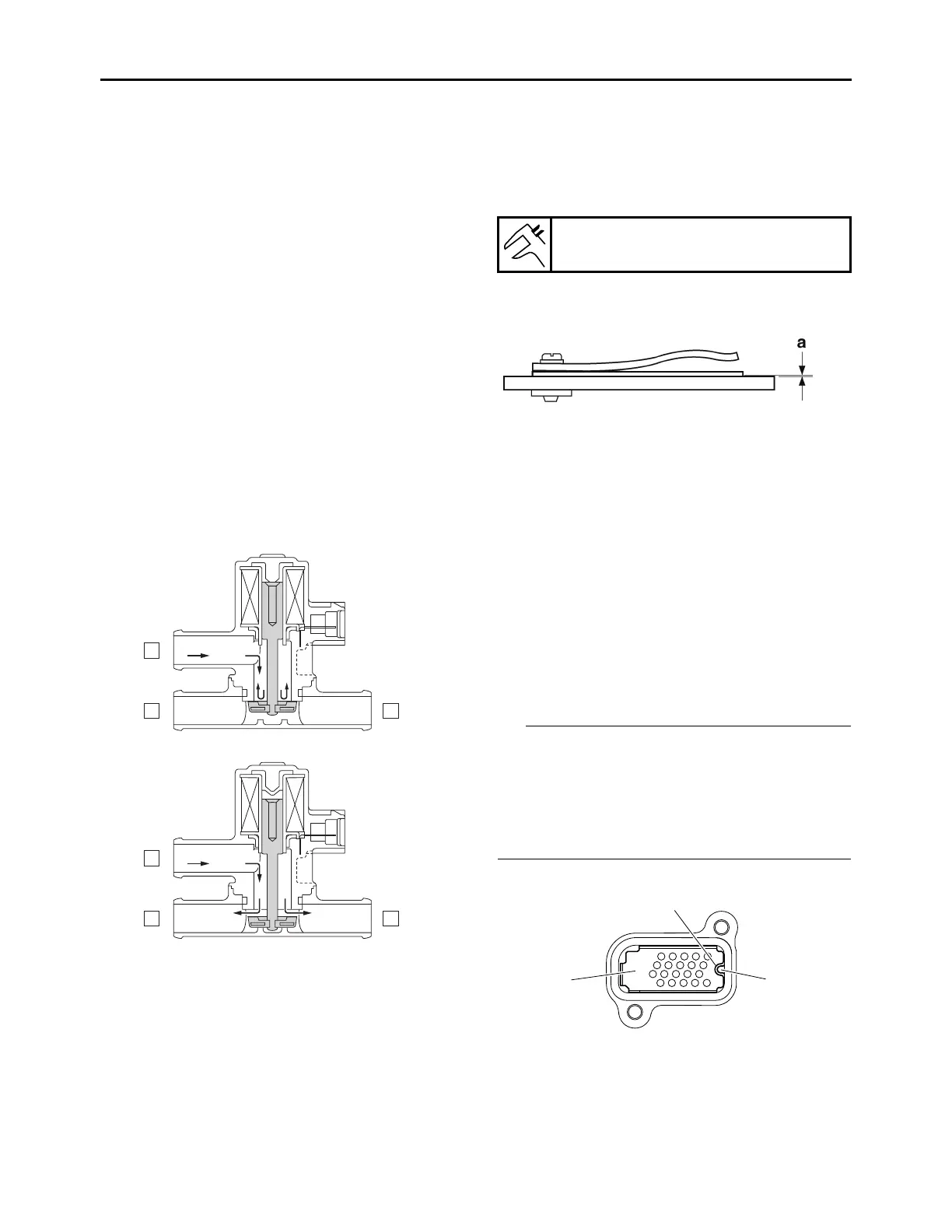
1. Install:
• Reed valve plate “1”
• Align the projection “a” on the cylinder head
cover with the notch “b” in the reed valve plate
“1”.
• Align the projection “c” on the cylinder head
cover with the hole “d” in the reed valve plate
“1”.
A. From the air filter case
B. To the cylinder head
Reed valve bending limit
0.4 mm (0.02 in)