P.O.Box 1, Hamamatsu, Japan
SERVICE MANUAL
101407
'18.03
IMPORTANT NOTICE
This manual has been provided for the use of authorized Yamaha Retailers and their service personnel.
It has been assumed that basic service procedures inherent to the industry, and more specifi cally Yamaha Products, are already known
and understood by the users, and have therefore not been restated.
WARNING:
Failure to follow appropriate service and safety procedures when servicing this product may result in personal injury,
destruction of expensive components, and failure of the product to perform as specifi ed. For these reasons, we advise
all Yamaha product owners that any service required should be performed by an authorized Yamaha Retailer or the
appointed service representative.
IMPORTANT:
The presentation or sale of this manual to any individual or fi rm does not constitute authorization, certifi cation or
recognition of any applicable technical capabilities, or establish a principle-agent relationship of any form.
The data provided is believed to be accurate and applicable to the unit(s) indicated on the cover. The research, engineering, and service
departments of Yamaha are continually striving to improve Yamaha products. Modifi cations are, therefore, inevitable and specifi cations
are subject to change without notice or obligation to retrofi t. Should any discrepancy appear to exist, please contact the distributor's
Service Division.
WARNING:
Static discharges can destroy expensive components. Discharge any static electricity your body may have
accumulated by grounding yourself to the ground buss in the unit (heavy gauge black wires connect to this buss).
IMPORTANT:
Turn the unit OFF during disassembly and part replacement. Recheck all work before you apply power to the unit.
Copyright (c) Yamaha Corporation All rights reserved.
This manual is copyrighted by Yamaha and may not be copied or
redistributed either in print or electronically without permission.
■ CONTENTS
TO SERVICE PERSONNEL ............................................2
FRONT PANELS .............................................................3
REAR PANELS ...............................................................5
REMOTE CONTROL PANEL ........................................ 10
SPECIFICATIONS /
参考仕様
....................................... 11
INTERNAL VIEW .......................................................... 15
SERVICE PRECAUTIONS /
サービス時の注意事項
..... 15
DISASSEMBLY PROCEDURES /
分解手順
................. 16
UPDATING FIRMWARE /
ファームウェアのアップデート
..................................20
SELF-DIAGNOSTIC FUNCTION /
ダイアグ(自己診断機能)
...........................................24
POWER AMPLIFIER ADJUSTMENT /
パワーアンプ調整
.......................................................62
DISPLAY DATA .............................................................63
IC DATA .........................................................................65
BLOCK DIAGRAMS ......................................................79
WIRING DIAGRAMS .....................................................81
PRINTED CIRCUIT BOARDS .......................................84
PIN CONNECTION DIAGRAMS ...................................96
CIRCUIT DIAGRAMS ....................................................97
REPLACEMENT PARTS LIST .................................... 109
REMOTE CONTROL ................................................... 132
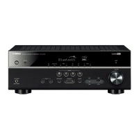
RX-V385/HTR-3072
Notes: When the DIGITAL P.C.B. or IC23 on DIGITAL P.C.B. is replaced, this unit will display “Internal Error” and
will not operate properly. The model name, destination and serial number MUST be written to the backup IC
(EEPROM: IC23 on DIGITAL P.C.B.) to have proper operation.
(For detailed procedure, refer to related Service News or Service Bulletin. Or contact your local Yamaha
representative.)
注意: DIGITALP.C.B. または DIGITALP.C.B. の IC23 を交換すると、“InternalError” が表示されて本機が正常に動作し
なくなります。正常に動作させるために、モデル名、仕向け先、シリアル番号をバックアップ IC(EEPROM:
DIGITALP.C.B. の IC23)へ書き込む必要があります。
(詳しい手順は、関連するサービスニュース、または技術報告を参照してください。もしくはヤマハのサービ
スセンターまでご連絡ください。)
AV RECEIVER
RX-V385/HTR-3072

 Loading...