 Loading...
Do you have a question about the Yamaha MC Series and is the answer not in the manual?
| Type | Analog |
|---|---|
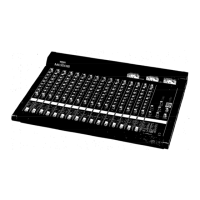
| Series | MC |
| Phantom Power | Yes |
| Dimensions | Varies depending on the model |
| Weight | Varies depending on the model |
| Outputs | Main L/R, Monitor, Aux, etc. |