EasyManua.ls Logo

Yamaha MG8/2FX Service Manual

Yamaha MG8/2FX
56 pages
To Next Page IconTo Next Page
Page #1 background imageLoading...
Page #1 background image
SERVICE MANUAL
PA
HAMAMATSU, JAPAN
Copyright (c) Yamaha Corporation. All rights reserved. PDF-K1941 MI ’04.12
011744
20050110-23000
CONTENTS(目次)
SPECIFICATIONS(総合仕様........................................................ 3/5
DIMENSIONS(寸法図)..................................................................... 7
CIRCUIT BOARD LAYOUT(ユニットレイアウト)........................... 7
PANEL LAYOUT(パネルレイアウト)................................................ 8
DISASSEMBLY PROCEDURE(分解手順)...................................... 11
LSI PIN DESCRIPTION(LSI 端子機能表)...................................... 15
IC BLOCK DIAGRAM(IC ブロック図)............................................ 16
CIRCUIT BOARDS(シート基板図)................................................ 17
INSPECTIONS(検査)................................................................ 22/27
BLOCK DIAGRAM & LEVEL DIAGRAM
(ブロック&レベルダイアグラム)
OVERALL CIRCUIT DIAGRAM(総回路図)
PA RTS LIST
w
w
w
.
x
i
a
o
y
u
1
6
3
.
c
o
m
Q
Q
3
7
6
3
1
5
1
5
0
9
9
2
8
9
4
2
9
8
T
E
L
1
3
9
4
2
2
9
6
5
1
3
9
9
2
8
9
4
2
9
8
0
5
1
5
1
3
6
7
3
Q
Q
TEL 13942296513 QQ 376315150 892498299
http://www.xiaoyu163.com

Other manuals for Yamaha MG8/2FX

Question and Answer IconNeed help?

Do you have a question about the Yamaha MG8/2FX and is the answer not in the manual?

Yamaha MG8/2FX Specifications

General IconGeneral
Number of Channels8
Microphone Inputs4
Line Inputs4
FX ProcessorYes
Phantom PowerYes
Aux Sends1
Headphone Output1
Main Outputs2
Equalizer3-band

Summary

Important Safety and Service Notices

Chemical Content and Handling Precautions

Product contains lead solder and other chemicals. Avoid ingestion and skin contact.

Specifications

Electrical Characteristics

Detailed electrical performance specs: distortion, frequency response, hum & noise, gain.

General Specifications

Overall product specs: filters, EQ, effects, indicators, meters, accessories, dimensions.

Specifications (Continuation)

Input Specifications

Detailed specs for input connectors, gain, impedance, sensitivity, and nominal levels.

Output Specifications

Detailed specs for output connectors, impedance, nominal levels, and clipping.

Panel Layout

Connector Pinout and Polarity

Disassembly Procedures

Bottom Case Disassembly

Step-by-step instructions for removing the bottom case and its components.

DSP Circuit Board Removal

Step-by-step instructions for removing the DSP circuit board.

Disassembly Procedures (Continued)

MAIN Circuit Board Disassembly

Step-by-step instructions for removing the MAIN circuit board and associated components.

MAIN Circuit Board Desoldering

Instructions for desoldering and removing wires from the MAIN circuit board.

Power Supply Switch and AC Connector Removal

Instructions for removing the power switch and AC connector.

Fuse Replacement

LSI Pin Description (CPU YMW767-V)

IC Block Diagrams

Inspections and Testing

Gain Specifications

Performance Testing Procedures

Frequency Characteristics Testing

Specifies frequency response ranges and measurement procedures for outputs.

Channel Equalizer Characteristics Testing

Tests EQ gain control effects on output levels across different frequencies.

Distortion Factor Testing

Measures total harmonic distortion at specified input/master levels and frequencies.

Performance Testing Procedures (Continued)

Distortion Factor Testing (Continued)

Distortion testing for C-R OUT and specific channel PAN/BAL configurations.

Maximum Output Level Testing

Checks distortion levels at maximum output signals for various outputs.
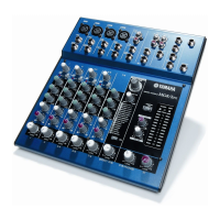
Circuit Diagrams Introduction

Block and Level Diagram (Overall)

Overall Circuit Diagram (Main 1/5)

Overall Circuit Diagram (Main 2/5)

Overall Circuit Diagram (Main 3/5)

Overall Circuit Diagram (Main 4/5)

Overall Circuit Diagram (Main 5/5)

Overall Circuit Diagram (DSP)

Related product manuals