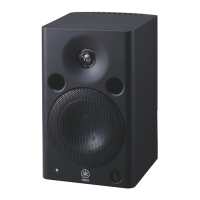
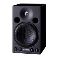
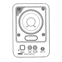
MSP5 STUDIO
9
[220A]
[220A]
[220B]
[220A]
[230], [240]
[230]
[220B]
[240]
[220A/B]: Bonding Tapping Screw-B 3x8 (WJ286400) +ボンディ
ングBタイト
[230]: Hexagonal Nut M12 (WJ285500) +6角ナット
[240]: Washer 12x16x0.6 (WJ286200) +ワッシャー
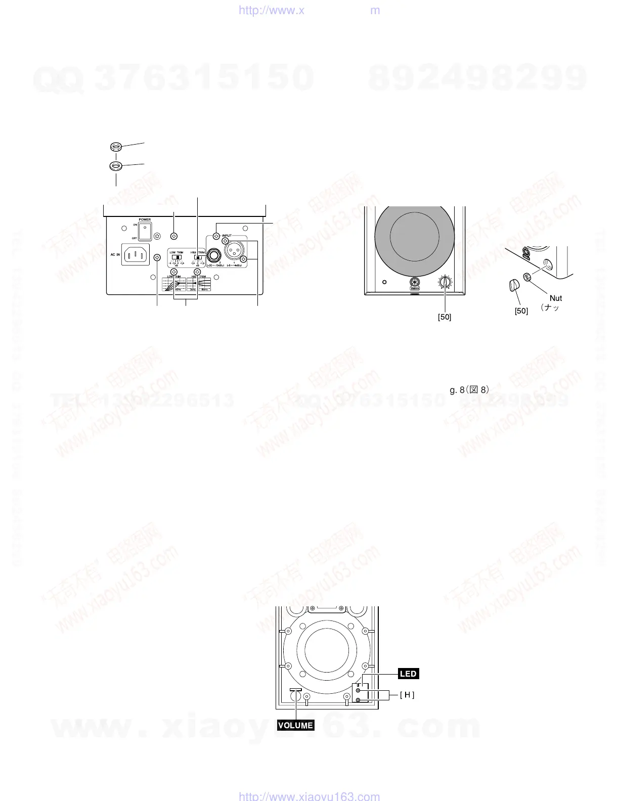
Fig. 7(図7)
6. VOLUME Circuit Board
(Time required: about 2 minutes)
6-1 Remove the rear panel assembly. (See procedure 2)
6-2 Remove the knob marked [50] and the nut.
The VOLUME circuit board can then be removed.
(Fig. 8)
7. LED Circuit Board
(Time required: about 2 minutes)
7-1 Remove the rear panel assembly. (See procedure 2)
7-2 Remove the two (2) screws marked [H]. The LED circuit
board can then be removed. (Fig. 9)
6. VOLUMEシート(所要時間:約2分)
6-1 リアパネルAssyを外します。(2項参照)
6-2 [50]のツマミとナットを外し、ボリュームシートを外
します。(図8)
7. LEDシート(所要時間:約2分)
7-1 リアパネルAssyを外します。(2項参照)
7-2 [H]のネジ2本を外し、LEDシートを外します。(図9)
Fig. 8(図8)
[50]: Knob Volume (WJ269800) ボリュームノブ
5-5 INPUTシート:
5-5-1 [220A]のネジ4本を外し、シールド金具を外します。
(図7)
5-5-2 [220B]のネジ3本、[230]の6角ナットおよび[240]の
ワッシャ−を外し、INPUTシートを外します。(図7)
5-5 INPUT Circuit Board:
5-5-1 Remove the four (4) screws marked [220A]. The bracket
shield can then be removed. (Fig. 7)
5-5-2 Remove the three (3) screws marked [220B], the nut
marked [230], and the washer marked [240]. The IN-
PUT circuit board can then be removed. (Fig. 7)
[H]
LED
VOLUME
Fig. 9(図9)
w
w
w
.
x
i
a
o
y
u
1
6
3
.
c
o
m
Q
Q
3
7
6
3
1
5
1
5
0
9
9
2
8
9
4
2
9
8
T
E
L
1
3
9
4
2
2
9
6
5
1
3
9
9
2
8
9
4
2
9
8
0
5
1
5
1
3
6
7
3
Q
Q
TEL 13942296513 QQ 376315150 892498299
TEL 13942296513 QQ 376315150 892498299
http://www.xiaoyu163.com
http://www.xiaoyu163.com