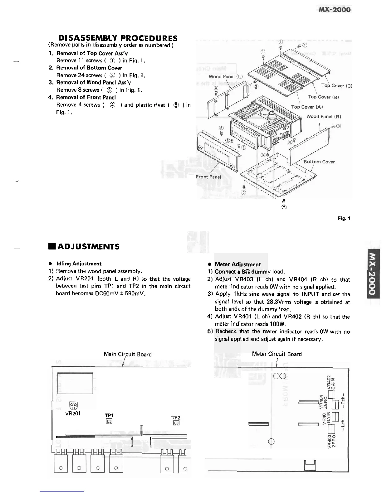
DISASSEMBLY PROCEDURES
(Remove parts in disassembly order as numbered.)
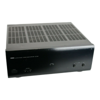
1. Removal of Top Cover
Ass'y
-
Remove 11 screws
(
@
)
in Fig.
1.
2.
Removal of Bottom Cover
Remove 24 screws
(
@
)
in Fig. 1.
3.
Removal of Wood Panel Ass'y
Remove 8 screws
(
@
)
in Fig. 1.
4.
Removal of Front Panel
Remove 4 screws
(
@
)
and plastic rivet
(
@
)
in
Fig. 1.
--
8
Q
Fig.
1
-
ADJUSTMENTS
Idling Adjustment
1) Remove the wood panel assembly.
2) Adjust VR201
(both
L
and R) so that the voltage
between
test
pins TP1 and TP2 in the main circuit
board becomes
DCGOmV
+
590mV.
Main Circuit Board
I
VR201
TPl
TP2
,
=
Meter Adj~
Connect a
.
,.
. .
,.
ustment
8.9
dumm
-.--
,.
1)
y load.
2)
Aalusr
vnrud
IL
ch) and VR404 (R ch) so that
meter indicator reads OW with no signal applied.
3) Apply 1kHz sine wave signal to INPUT and set the
signal level so that
28.3Vrms voltage
is
obtained at
both ends of the dummy load.
4)
Adjust VR401
(L
ch) and VR402 (R ch) so that the
meter indicator reads 1OOW.
5)
eter indicator reads OW with no
iust again if necessary.
Recheck
t
signal appl
hat the m
ied and
adj
lvlerer Circuit Board
1