Do you have a question about the Yamaha P1500 and is the answer not in the manual?
Keep the unit away from high temperatures, humidity, dust, and vibration to prevent damage.
Handle the unit with care to prevent damage from physical shocks.
Do not open the case or attempt repairs; refer all maintenance to qualified service personnel.
Always turn the power OFF before connecting or disconnecting cables to prevent equipment damage.
Always plug and unplug cables by gripping the connector, not the cord.
Clean the unit with a soft, dry cloth only. Never use solvents.
Ensure the power supply voltage matches local mains and can deliver sufficient current.
Instructions for connecting the plug and cord in the UK, matching wire colours to terminals.
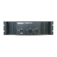
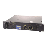
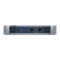
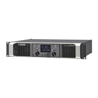
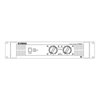
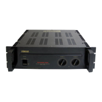
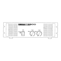
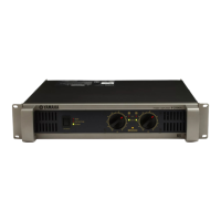
Details the POWER switch, PROTECTION, SIGNAL, CLIP indicators, and input attenuators on the front panel.
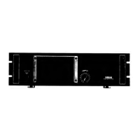
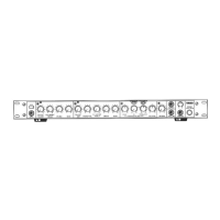
Describes XLR, 1/4" phone, and barrier strip input terminals for channels A and B.
Details the two types of speaker output terminals (binding posts, barrier strip) and polarity for STEREO/BRIDGE modes.
Explains the function of the STEREO-BRIDGE slide switch for selecting operating mode.
Describes independent operation of channels A and B in stereo mode, with minimum 4 Ω speaker impedance.
Explains bridged operation of channels A and B as a single mono amplifier, with minimum 8 Ω speaker impedance.
Details minimum speaker impedance for STEREO and BRIDGE modes, including parallel connections.
Explains the need for speaker fuses and how to calculate the required fuse capacity based on impedance.
Recommendations for selecting speaker cable thickness to maintain signal integrity and performance.
Instructions for portable rack mounting, ensuring proper ventilation for front and rear panels.
Addresses causes and remedies for the CLIP indicator lighting up, related to signal or shorts.
Explains causes and remedies for the PROTECTION indicator, such as overheating or DC voltage.
Detailed technical specifications for P3500, P2500, and P1500 models, including power output, frequency response, and distortion.
Illustrates the internal signal flow and protection circuits of the amplifier.
Provides physical dimensions of the amplifier unit in millimeters.
Presents graphs showing power consumption versus output power for different models and conditions.