I
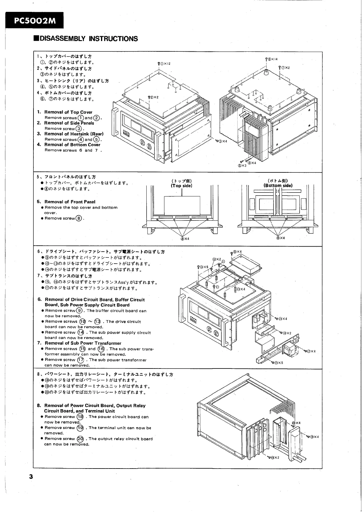
.DISASSEMBLY INSTRUCTIONS
2,
tt-i
E'/I=+JLOlMfLft
Om$P&ibfLdf.
3,
k-
1.929
('l7')
OlMf
l.3
@.
@o,+'iflbf Ldb.
4,
*
t-
lrnlr-mM+
LA
8.
0m+5%ttfLdb0
1.
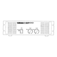
Removal of Top Cover
Remove screws
a
and
0.
Remove screws
6
and
7
.
5,
7a>E/cw~coltf Lft
b
~Y7'A/\'--.
*
b.LA~\'--&CtfLdf.
@@O)+'i&lbfLdb.
5.
Removal of Front Panel
Remove the top cover and bottom
a@mlr.~%~$f'ift:/f~~77
9-
bh'Cbfhb
to
a@-om+'iaisfb1: ~4.r~~- bt~li~11.d~~
@@~+'i&CbfbtV7'@B9- bVlbfhdb,
7,
tt7'F5>XOltf Lh
0.
@m+'i&Cifbt:Vy
b
4 :,zAssSy Vlbfhdb.
@OO)+'i%Cif
ttV7'b 4>~7YCifhbt,
6.
Removal of Drive Circuit Board, Buffer Circuit
Board, Sub Power Supply Circuit Board
Remove screw@. The buffer c~rcuit board can
now be removed.
Remove screws
@
-
@
.
The drive circuit
board can now be removed.
Remove screw
@
.
The sub power supply circu~t
board can now be removed.
@@m;t.'if ldf .tfC;Y9- 5t)l.1=~ bVtZfh2.t.
.@m+'i<felb~h
'I
b-9-
btFCbfhbt.
8.
Removal of Tower Circuit Board, Output Relay
Circuit Board, and Terminal Unit
Remove screw
@
.
The power circuit board can