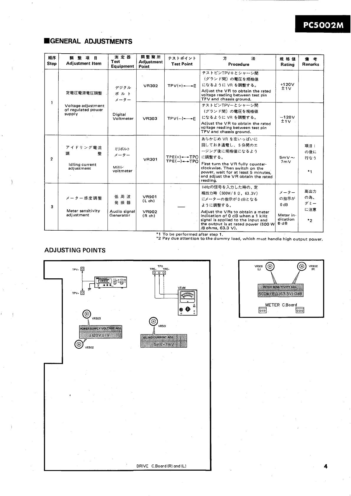
.GENERAL ADJUSTMENTS
ADJUSTING POINTS
TPO
TPV-
TPE-
TPE.
0
0
DRIVE C.Boord lR1 and lL1
IIRR
Step
'
2
3
'2 Pay due attention to the dummy load, which must handle high output power.
BBP*
Adjustment
Point
VR30.2
VR303
VR301
VR901
(Lch)
VR902
(R ch)
*I
R
B
4i
R
Adjustment item
X@mE%@E%%
Voltage adjustment
of regulated power
supply
P-rP1)>Ya;3
=
Idling current
adjustment
j-s-@,-ga%
Meter sensitivity
adjustment
tx~iti'.f2~
Test
Point
TPV(+)-E
TPV(-)-E
TPE(+)-TPO
TPE(-)-TPO
-
To be performed
12s
Equipment
79
9
Jb
*
lb
I.
3-7-
Digital
Voltmeter
2l)*]bt.
3-7-
Milli-
voltmeter
"El
;&
st^^
Audio signal
Generator
R
$55
Procedure
72
I.
L0>TPV+C .i~--Z/fL7
(r?>
FB~) mt~frfi39rfs
i:?dB&
i
1-
VR
fr%Et6,
Adjust the VR to obtain the rated
voltage reading between test pin
TPV and chassis ground.
7X
I.
Y>TPV-CZ/T-LW~~
(Y7> FB-7) m@E&-3R%f&
iCfd6
&
i
r=
VR
&-%Ebb,
Adjust the VR to obtain the rated
voltage reading between test pin
TPV and chassis ground.
&r;*Cdl,
VR
frzL\7lfL\i=
HLTi=jBi&tL, 593b7mr
-9>5fbizR%@i:fd6.k
i
i=%!?&66,
First turn the VR fully counter-
clockwise. Then switch on the
power, wait for at least 5 minutes,
and adjust the VR obtain the rated
reading.
IkHzmW+%&-h%I Lf:i%Fm, X
~ttrm
(soow/a
n,
63.3~)
i=%-9-~7ltS%v
0
dB2 fd6
dr
i
i:%E?f6,
Adjust the VRs to obtain a meter
indication of 0 dB when a 1 kHz
signal is applied to the input and
the output is at rated power (500
W
/8
ohms, 63.3 V).
after step
1.
gem
Rating
+I
20v
+1V
-1 20v
+Iv
5mV-
7rnV
$9-
0
dB
Meter
in-
dication
O
dB
tik
4
Renarks
a1
I
cnf%i:
77fd:
j
*
1
8x71
ma.
7' 2
-
i:
;it
*2