16
PSR-1500/PSR-3000
11. Speaker Grille L Assembly
(Time required: About 4 minutes)
11-1. Remove the lower case assembly. (See procedure 1.)
11-2. Restraighten the eight (8) projections marked [A] to come
off the slots of the upper case assembly. (Fig. 2)
11-3. Remove the Speaker Grille L assembly. (Fig. 1)
12. Speaker Grille R Assembly
(Time required: About 4 minutes)
12-1. Remove the lower case assembly. (See procedure 1.)
12-2. Restraighten the eight (8) projections marked [B] to come
off the slots of the upper case assembly. (Fig. 2)
12-3. Remove the Speaker Grille R assembly. (Fig. 1)
13. Keyboard Assembly
(Time required: About 3 minutes)
13-1. Remove the lower case assembly. (See procedure 1.)
13-2. Remove the two (2) screws marked [430B]. The keyboard
assembly can then be removed. (Fig. 2)
14. INV Circuit Board
(Time required: About 4 minutes)
There may be high voltage components. Make
sure to disassemble the components after
turning the power switch off.
14-1. Remove the lower case assembly. (See procedure 1.)
14-2. Remove the four (4) screws marked [460E]. The INV
circuit board can then be removed. (Fig. 2)
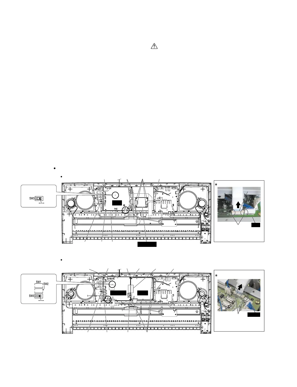
15. DM Circuit Board (PSR-1500), DM2-E
Circuit Board (PSR-3000), DAC1A
Circuit Board, TG1 Circuit Board (PSR-
3000)
15-1. Remove the lower case assembly. (See procedure 1.)
15-2. Remove the four (4) screws marked [440A], the seventeen
(17) screws marked [460F], the three (3) screws marked
[560C] and the three (3) screws marked [570]. The shield
cover L with the INV circuit board can then be removed.
(Fig. 2) (PSR-1500)
15-3. Remove the four (4) screws marked [440A], the nineteen
(19) screws marked [460F], the three (3) screws marked
[560C] and the screw marked [570]. The shield cover L
with the INV circuit board can then be removed.
(Fig. 2-1) (PSR-3000)
* When DM circuit board (PSR-1500) or DM2-E circuit board (PSR-3000) is replaced, data on Internet settings may be lost.
* DM circuit board (PSR-1500) and DM2-E circuit board (PSR-3000) have an internal DIP switch for switching the display in
Japanese or in English (SW3).
[460H]
[460H]
[460H]
[460G]
Shield cover U
[460G]
[460K]
[460G]
Shield cover U
[460G]
DM
DAC1A
[460L]
TG1
[460J]
[460J]
[460L]
[460J][460J]
Connector
DM2-E
• DIP Switch
Japanease English
• DIP Switch
Japanease English
1
1
Howtoremoveconnectors
2
Howtoremoveconnector
Retainer
Pull up the retainer section
and remove the connector.
Retainer
Pull up the retainer section
and remove the connector.
2
DM2-E
DM
CN10CN10
CN7CN7
(Fig. 3)
[460]: Bind Head Tapping Screw-B 3.0X8 MFZN2Y(EP600250)
PSR-3000
PSR-1500
Bottom view
 Loading...