11
PSR-S650
No.
UnitName
(ユニット名)
Location
(ロケーション)
PartsNo.
(部品番号)
ConnectorAssembly
(束線名)
Destination
(配線先)
Remarks
(備考)
q
UPPER CASE
ASSEMBLY
300 WU967500 LCD UNIT LCD UNIT *1 DM-CN2 *2 14P
w
-1
460 (WW95890) TW
TW (Right) *4 AM-CN404 *3
2P L=520
w
-2
TW (Left) *4 AM-CN405 *3
e
500 WW959800 FFC CABLE PNC-CN104 *2 AM-CN401 *2 8P L=65
r
510 (WW96010) BL LCD UNIT *4 DM-CN10 *3 2P L=230
t
520 WW956200 FFC1 PNC-CN102 *2 PNR-CN301 *2 15P L=75
y
530 WW956300 FFC2 PNC-CN103 *2 PNL-CN204 *2 27P L=85
u
540 WW959700 FFC CABLE DM-CN3 *2 PNC-CN106 *2 9P L=80
i
560 WW959900 FFC CABLE DM-CN7 *2 AM-CN402 *2 22P L=50
o
LOWER CASE
ASSEMBLY
30 (WZ22380) SP
SPEAKER (Woofer) (Right)
*5
AM-CN406 4P L=480
SPEAKER (Woofer) (Left)
*6
!0
LOWER KEY BED
ASSEMBLY
20c WW724300 MK1-11 61H-MK-CN1 *3 DM-CN6 *3 12P L=245
!1
20d WE13870R MK2 61H-MK-CN2 *3 DM-CN4 *3 5P L=250
!2
20e WE13880R MK3 61L-MK-CN5 *3 DM-CN5 *3 7P L=190
!3
KEYBOARD ASSEMBLY
220 V869620R 61H-MK-CN3 *3 61L-MK-CN4 *3 12P L=210
!4
MVR CIRCUIT BOARD
WH501 (WW95920) MVR MVR-CN501 *1 PNL-CN202 *3 5P L=70
!5
PB CIRCUIT BOARD
WH601 (WW95960) PB PB-CN601 *1 PNL-CN203 *3 3P L=150
!6
ENC CIRCUIT BOARD
WH701 (WW95900) ENC ENC-CN701 *1 PNC-CN107 *3 3P L=75
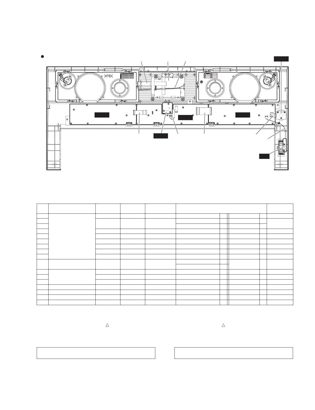
Upper case assembly
(上ケース Assy)
PNR PNL
PNC
ENC
MVR
PB
LCD UNIT
(液晶ユニット)
=
: ;
B
* The parts with “( )” in “Part No.” are not available as spare parts.
*1: Connected
*2: The conductor of a cable and the point of contact of a connector are untited.
*3: Edge mark is adjusted to Pin 1 mark ( mark).
*4: Edge mark is adjusted to + mark.
*5: Red wire is connected to (+) terminal. Black wire is connected to (–) terminal.
*6: White wire is connected to (+) terminal. Black wire is connected to (–) terminal.
Caution: Be sure to attach the removed fi lament tape just as it
was before removal.
*部品番号が()で囲まれている部品は、サービス部品として準備されていません。
*1: 接続済み
*2: 電線の導体とコネクタの接点を合わせる
*3: エッジマークが 1 ピン側( )
*4: エッジマークが + 側 (+)
*5: 赤色線材が(+)端子、黒色線材が(‒)端子
*6: 白色線材が(+)端子、黒色線材が(‒)端子
注意 :一度剥がしたフィラメントテープは、取り外す前と同じよ
うに、取り付けてください。
 Loading...