I/O devices and external head amps
V5.1 Supplementary Manual
8
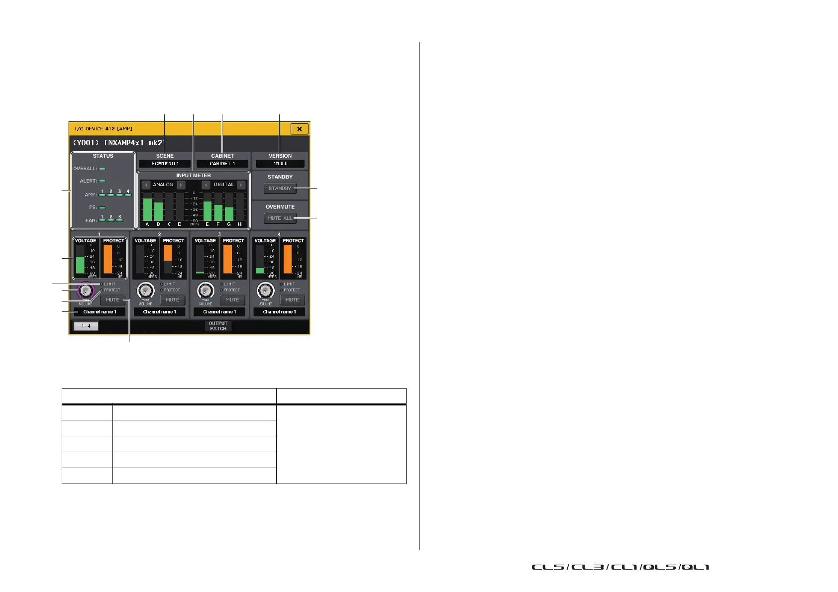
I/O DEVICE EDIT screen
This screen is displayed when you select the desired I/O device in the I/O DEVICE screen
(AMP page). You can remotely control the amplifier or the speakers.
For NEXO NXAMPmk2
1
STATUS indicator
Indicates the status of the device.
* ALERT indicator display is green and red only. When an alert occurs, the indicator turns red and the alert
contents are displayed at the bottom of the screen.
2 SCENE
Displays the recalled scene number and title.
3 CABINET
Displays the name of NEXO Setup selected in the NXAMP.
4 VERSION
Displays the firmware version of the device.
5 INPUT METER
Displays both the input analog input levels and digital input levels.
6 STANDBY button
Switches the standby mode on or off.
7 OVERMUTE button
Switches the over mute (mute all channels) on or off.
8 Output level meter
Displays the output level of the channel.
9 VOLUME knob
Sets the channel volume.
0 LIMIT indicator
Lights while the limiter for amplifier or power supply protection is applied.
A PROTECT indicator
Lights while the limiter for speaker protection is applied.
B MUTE button
Switches the channel mute on or off.
C Channel name
Displays the channel name (the speaker preset name for the NXAMP).
Status Indicator display
OVERALL Overall status of the device
Green: Normal operation
Yellow: Fault detection
Orange: Temporary malfunction
Red: Malfunction that cannot
be resolved
ALERT Alert
AMP Operating status of each amplifier channel
PS Operating status of power supply unit
FAN Operating status of each FAN unit

 Loading...