
J
Jerry OwensAug 1, 2025
What to do if Yamaha Robotics has major software errors?
- Ssteven27Aug 1, 2025
If you encounter major software errors with your Yamaha Robotics system, reinstall or update the software.
What to do if Yamaha Robotics has major software errors?
If you encounter major software errors with your Yamaha Robotics system, reinstall or update the software.
What to do if Yamaha Robotics shows memory errors?
If Yamaha Robotics displays memory errors, check the memory usage and clear any unnecessary data.
How to resolve Yamaha Robotics robot language syntax errors?
To resolve robot language syntax errors (compiling) in Yamaha Robotics, review the program code for syntax errors and correct them.
What to do if Yamaha Robotics has data entry and edit errors?
If you encounter data entry and edit errors with your Yamaha Robotics, verify data entries and make necessary corrections.
What to do if Yamaha Robotics shows memory card errors?
If Yamaha Robotics displays memory card errors, check the memory card for damage and ensure it is properly inserted.
What to do if Yamaha Robotics has RPB errors?
If Yamaha Robotics is showing RPB errors, restart the RPB and check connections.
General precautions for safe and correct use of YAMAHA robots and controllers, and warnings about potential hazards.
Explains the meaning of DANGER, WARNING, CAUTION, and NOTE symbols used for safety instructions.
Describes warning labels attached to the robot body and controller to alert operators to potential hazards.
Details specific warning messages and instructions for Danger, Warning, and Caution labels on robots and controllers.
Explains warning symbols for electrical shock hazard, high temperature hazard, and general caution.
Describes major precautions for using robots and controllers throughout their life cycle.
General precautions for safe use, including applications where robots cannot be used and operator qualifications.
Precautions for moving and installing robots, including installation environment and moving procedures.
Precautions for robots regarding installation environment (magnetic fields, interference, flammable gases) and moving procedures.
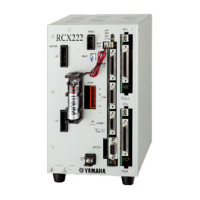
Precautions for robot controllers concerning installation environment, installation, and connections.
General safety measures including referring to warning labels, creating work instructions, and taking basic safety actions.
Details safety measures such as referring to manuals, understanding work instructions, and taking basic safety actions.
Instructions on installing a safety enclosure to prevent contact with moving parts and potential injuries.
General safety measures and checks to ensure safe robot operation.
Procedures for performing trial operation after installation, including safety enclosure requirements and pre-operation checks.
Checkpoints before starting automatic operation and procedures when errors occur.
Precautions during operation, including handling damage, abnormal conditions, and high temperatures.
Guidelines for performing daily and periodic inspections, pre-operation checks, and record keeping.
Precautions before starting inspection or maintenance, including not attempting un-described work and contacting distributors.
Precautions during service work, such as removing motors, handling magnets, pneumatic equipment, and cooling fans.
Describes emergency actions to release the robot axis if a person is caught between the robot and mechanical parts.
General guidance on safely using the robot.
Describes protective functions for YAMAHA robots, including overload detection, overheat detection, soft limits, and mechanical stoppers.
Stresses the need for appropriate training and skills for personnel handling robots for tasks like teaching and maintenance.
Emphasizes secure connection to the ground terminal for safety and noise prevention.
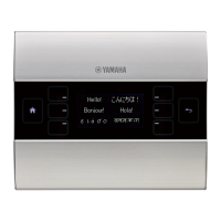
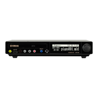
Describes the RPB as a hand-held device for robot operations, including manual operations, program input, editing, teaching, and parameter settings.
Outlines the basic sequence from installation to actual operation, including wiring, power on, initial settings, data setting, and trial operation.
Lists installation conditions and cautions for carrying, connector handling, cable length, panel installation, environmental factors, and fan vents.
Lists installation conditions and cautions for carrying, connector handling, cable length, panel installation, environmental factors, and fan vents.
Provides an example connection diagram for supplying power to the controller, including leakage breaker, noise filter, and contactor.
Provides an example connection diagram for supplying power to the controller, including leakage breaker, noise filter, and contactor.
Details power supply voltage specifications, wire cross-sections, grounding requirements, and tightening torque for terminals.
Explains how to connect robot cables to the controller's XM, YM, and ROB I/O connectors, with important warnings.
Details connecting robot cables to controller connectors and emphasizes checking for damage and proper grounding.
Explains how to connect the RPB to the controller's RPB connector and the importance of using a terminator if the RPB is not connected.
Guides on connecting absolute batteries to the BAT A or BAT B connector for data retention, explaining backup time with one or two batteries.
Explains how to check controller operation after making connections, using a special connector and applicable robot.
Details the cable connections required before checking controller operation, including power supply, robot cable, RPB, and safety connector.
Describes how to check controller operation after turning on power, distinguishing between normal and abnormal operation based on LED indicators.
Describes the RPB programming box, its part names, main functions, connection to the controller, and screen settings adjustment.
Details connecting the RPB programming box to the controller's RPB connector and securing the cable.
Explains how to turn the robot controller power on and off, assuming external circuits are correctly connected.
Explains how to press the emergency stop button on the RPB to immediately stop robot operation and displays the resulting screen message.
Guides on how to reset the emergency stop status to return to normal operation, including canceling the flag and turning on motor power.
Explains how to reset overload errors to restore robot operation, including the requirement for software version 9.36 onwards.
Describes the robot operation modes: SERVICE, AUTO, PROGRAM, MANUAL, and SYSTEM, and how to select them.
Classifies robot operation into five basic modes: SERVICE, AUTO, PROGRAM, MANUAL, and SYSTEM, and how to select them.
Explains that SERVICE mode is used for safe maintenance work within the safety enclosure, with specific limitations on operation and speed.
Explains that AUTO mode executes robot language programs and related tasks, showing the initial AUTO mode screen.
Details continuous program command execution during automatic operation, emphasizing prerequisites like return-to-origin and debugging.
Explains how to edit, delete, and manage robot language programs in PROGRAM mode, showing the initial screen.
Details how to enter program editing mode, move the cursor, enter commands, and finish editing.
Explains connecting a 24V DC power supply to the DIO option board's power connector.
Explains the robot controller's SAFETY I/O interfaces for compatibility and describes I/O terminals and connection methods.
Illustrates emergency stop input signal connections for standard RPB and RPB-E with external circuits.
Lists robot controller error messages classified by group number, detailing code, meaning/cause, and action.
Lists robot controller error messages classified by group number, detailing code, meaning/cause, and action.
Details errors related to robot operating area, such as over soft limit, missing standard coordinates, and failed calibrations.
Lists syntax errors encountered during robot language compiling, such as syntax errors, data errors, and illegal commands.
Details execution errors in robot language, including illegal commands, task errors, and path errors.
Lists errors related to memory issues, such as program destroyed, point data destroyed, and memory full.
Covers errors related to system settings or hardware, like robot disconnected and driver unit version mismatches.
Lists errors related to I/O and option boards, such as communication errors and hardware failures.
Details errors specific to the RPB, including communication errors, parity errors, and version mismatches.
Lists errors related to motor control, including watchdog errors, over current, over load, and servo errors.
Lists major software errors such as system errors and watchdog errors.
Lists major hardware errors like AC power low, DC24V power low, and abnormal voltage/temperature.
Provides guidance on troubleshooting common issues, including symptoms, causes, check items, and corrective actions.
Explains methods for acquiring error information from the RPB or via RS-232C connection to a PC.
Provides a table of common symptoms, possible causes, check items, and corrective actions for installation, power supply, and robot operation issues.
| Controlled axes | 4 axes |
|---|---|
| I/O points | Input: 32 points, Output: 32 points |
| Communication interface | RS-232C |
| Operating Voltage | 24 VDC ±10% |
| Operating Temperature | 0°C |