Do you have a question about the Yamaha RCX240 and is the answer not in the manual?
Explains safety precautions and operating points using symbols and signal words like DANGER, WARNING, CAUTION, and NOTE.
Provides critical cautions for handling and operating the robot and controller, covering system design, installation, wiring, start-up, maintenance, and disposal.
Details specific safety measures for SCARA, single-axis, Cartesian, and pick & place robots, including motor overload precautions and warning labels.
Explains the importance of correctly setting controller parameters to match the motor type to prevent abnormal operation and motor overload.
Describes warning labels affixed to the controller, emphasizing the importance of observing instructions and cautions on the labels for safe operation.
Specifies the training and skills required for operators and maintenance personnel handling industrial robots, emphasizing manual review.
Highlights the necessity of performing daily and periodic inspections and pre-work checks to ensure the robot and equipment are free of problems.
Provides instructions on how to safely free a person caught between the robot and mechanical parts or by the robot.
Details warranty information, including coverage, exclusions, and YAMAHA's liability disclaimer.
Specifies operating conditions such as temperature, humidity, and environments to avoid to ensure controller safety and performance.
Provides an overview of the RCX series controllers and their applications, including multi-tasking and interpolation functions.
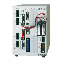
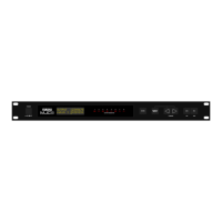
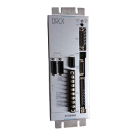
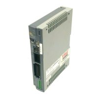
Shows the external view of the RCX240 and its basic block diagram, illustrating the controller's system layout and components.
Describes optional devices like the RPB programming box, expansion I/O board, and regenerative unit that enhance controller functionality.
Outlines the essential steps from installation to operation, covering connections, power, robot type check, parameter settings, and trial runs.
Defines axis terminology for the RCX240 controller, including main, sub, and auxiliary axes, and their respective commands.
Provides instructions for unpacking the robot controller and checking accessories, with safety precautions for handling heavy equipment.
Details the process of installing the robot controller, including selecting a proper location and adhering to installation conditions.
Identifies and explains the function of various connectors on the robot controller, crucial for proper system integration.
Guides on connecting the power supply to the robot controller, including examples and necessary components like breakers and filters.
Instructions for connecting robot cables to the controller, emphasizing correct identification and separation from power cables.
Details the connection of the RPB programming box to the controller, stressing correct orientation and the use of a terminator.
Explains how to connect various I/O signals from peripheral equipment to the robot controller, including NPN/PNP specifications.
Guides on connecting a host computer to the robot controller using the RS-232C interface, detailing cable requirements.
Provides instructions for connecting absolute batteries to the controller, explaining connection methods and backup times.
Details the procedure for replacing the absolute battery when it wears down or data backup issues arise.
Explains how to connect a regenerative unit to the controller for energy recovery.
Offers guidelines for safe cable routing and installation, emphasizing separation of cables to prevent noise and malfunctions.
Guides on checking controller operation after connections, verifying LEDs, and interpreting error messages.
Explains the controller configuration and main functions, including RPB usage and system overview.
Identifies the front panel parts of the RCX controller and explains the main functions of its terminals and LEDs.
Details the RPB programming box, including its display, keys, emergency stop button, and connector.
Provides instructions for turning the power on and off, assuming correct external circuit connections and controller operation.
Explains the RPB screen layout and operation keys, categorizing them into function, control, and data keys.
Explains the use of the emergency stop button on the RPB to immediately halt robot operation and cut off power.
Classifies robot operation into basic modes (SERVICE, AUTO, PROGRAM, MANUAL, SYSTEM) and explains other modes.
Details SERVICE mode operations, including safety precautions, speed limitations, and the Hold-to-Run function.
Introduces AUTO mode for executing robot programs, explaining screen components and operations like automatic speed change and point trace.
Details PROGRAM mode operations for editing, deleting, and managing robot language programs, including listing, editing, and directory functions.
Explains MANUAL mode operations for defining and editing point data, shift coordinates, hand definitions, and pallet definitions.
Introduces SYSTEM mode for controlling operating conditions, covering parameters, configurations, and system diagnostics.
Defines two-robot setting as a configuration controlling two robots with one controller, enabling multi-task function.
Explains operations and data types specific to the two-robot setting, covering AUTO mode, MANUAL mode, SYSTEM mode, and programming.
Details robot languages and commands used in two-robot settings for operation, coordinate control, and programming.
Provides an overview of the standard I/O interface, including power supply, connectors, signals, and timing charts.
Details the option I/O interface, covering ID settings, power supply, connectors, signals, and general-purpose I/O.
Lists electrical ratings for input and output signals, including voltage, current, response time, and contact service life.
Highlights important cautions related to I/O connections, including sensor usage, inductive loads, noise prevention, and power supply.
Provides an overview of the SAFETY I/O interface, including power, connectors, signals, and connection methods.
Lists PIN, I/O No., Signal name, Description, and Remarks for the SAFETY connector.
Shows exploded views of the SAFETY connector, illustrating connection and solder sides with pin numbers.
Details connections for external emergency stop circuits with RPB and RPB-E, including safety cautions.
Illustrates typical input signal connections for NPN and PNP specifications.
Describes dedicated input signals like SERVICE mode, emergency stop, enable switch, program start, AUTO mode, return-to-origin, and program reset inputs.
Details dedicated output signal connections for NPN and PNP specifications.
Explains the meaning of dedicated output signals like CPU_OK, Servo ON, Alarm, AUTO mode output, and return-to-origin complete.
Explains the robot controller's communication capabilities with external devices via RS-232C interface in ONLINE and OFFLINE modes.
Details the two communication modes: OFFLINE (using SEND commands) and ONLINE (direct commands from external unit).
Lists communication parameters including transmission mode, baud rate, character length, stop bit, parity, and termination code.
Provides cautions regarding communication, including receive buffer handling, external device power sequence, handshake protocols, and noise.
Presents a character code table in hexadecimal format, explaining various codes and their meanings.
Shows examples of connecting the robot controller to a PC using COM port or USB port with YAMAHA communication cables.
Covers essential inspections and precautions before starting robot operation and periodic maintenance.
Describes periodic inspections for the controller, including daily and three-month checks.
Provides instructions for checking and replacing the fan filter on the controller's rear panel.
Lists maintenance parts subject to wear, such as absolute battery and fan filter, including part numbers.
Lists basic specifications for the RCX240 and RCX240S controllers, including dimensions, power, and axis control.
Details the controller's basic functions, including operation modes, commands, functions, variables, and monitors.
Shows external views of the RCX240 and RCX240S controllers, illustrating dimensions, connectors, and mounting options.
Lists basic specifications and shows external views of the RPB and RPB-E programming boxes, covering features and dimensions.
Provides a comprehensive list of robot controller and RPB error messages, including codes, meanings, causes, and actions.
Guides on general troubleshooting procedures, how to acquire error information, and common checkpoints for resolving issues.
| Brand | Yamaha |
|---|---|
| Model | RCX240 |
| Category | Controller |
| Language | English |