Do you have a question about the Yamaha ERCX Series and is the answer not in the manual?
Details the key features of the ERCX controller, including its CPU, absolute method, compatibility, and I/O capabilities.
Outlines the basic steps required to set up the ERCX controller for use, from installation to programming.
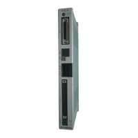
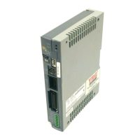
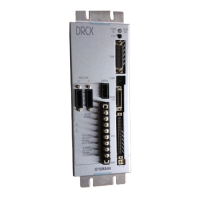
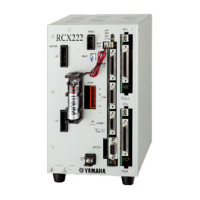
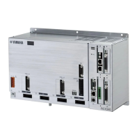
Identifies and describes the external components and connectors of the ERCX controller and TPB.
Illustrates the system configuration diagram showing how the ERCX controller connects with peripheral units.
Lists the standard accessories included with the ERCX controller and available optional peripheral units.
Provides instructions and precautions for installing the ERCX controller, including location and method.
Details the power requirements and connection procedures for the ERCX controller, including cautions.
Explains the importance of proper grounding for the ERCX controller to prevent electrical shock and noise.
Describes how to connect the ERCX controller to the TPB programming box or a PC for operation.
Outlines the procedure for connecting the robot cable to the ERCX controller, including signal table.
Explains how to connect external equipment, such as a PLC, to the ERCX controller's I/O connector.
Details the procedure for connecting the absolute battery, which is essential for maintaining position data.
Lists and describes all individual signals assigned to the 48 pins of the standard I/O connector.
Explains the functions of dedicated command inputs, general-purpose inputs, interlock, and emergency stop inputs.
Describes the dedicated and general-purpose output signals used for exchanging information with external devices.
Provides specifications and connection examples for the ERCX controller's I/O circuits, including input and output circuits.
Shows general I/O connection diagrams, including connections to Mitsubishi PLC output and input units.
Presents typical timing charts for I/O control to aid in creating sequence programs.
Explains how to change the function assigned to each I/O signal using parameter settings.
Details the procedures for connecting and disconnecting the TPB programming box to the ERCX controller.
Explains fundamental key operations and menu navigation on the TPB for interacting with the controller.
Describes the meaning of various displays on the TPB screens, such as program execution and edit screens.
Provides a visual representation of the TPB's menu hierarchy for navigating functions and settings.
Explains how to set access levels to restrict TPB key operations for safety and preventing accidental changes.
Guides users on how to set and change controller parameters using the TPB.
Provides detailed descriptions of all available parameters, their functions, input ranges, and default values.
Introduces the YAMAHA robot language, point data, and the controller's program specifications.
Details procedures for creating, changing, copying, and deleting programs using the TPB.
Covers utility functions for managing programs, such as copying, deleting, and viewing program information.
Explains how to enter point data directly using the TPB number keys.
Describes how to move the robot to a position and record it as point data using teaching playback.
Details the process of teaching point data by manually moving the robot and using the emergency stop button.
Explains how to manually control general-purpose outputs from the TPB for operating external devices.
Describes how to release the holding brake on the vertical type robot for manual adjustment.
Provides instructions on how to delete point data from the controller using the TPB.
Explains how to move the robot to a registered data point to check input point data.
Lists all available robot language commands with their descriptions and formats.
Explains the syntax rules for writing robot language command statements, including operands and comments.
Covers advanced program functions such as multi-tasking and limitless movement.
Provides detailed descriptions of individual robot language commands, their functions, formats, and examples.
Offers sample programs for various robot operations and applications for user reference.
Details methods for performing return-to-origin using search and mark methods.
Explains how to operate the robot one step at a time using the TPB.
Describes how to run the robot program automatically from beginning to end.
Guides on how to switch the active program for automatic operation.
Explains how to initiate and recover from an emergency stop using the TPB and I/O inputs.
Shows how to display the ON/OFF status of memory I/O signals on the TPB screen.
Explains how to display the values of point, counter, and flag variables on the TPB.
Details the procedure for initializing programs, points, and parameters to their default values.
Explains how to view the ON/OFF status of digital I/O signals on the TPB screen.
Describes how to display controller version, TPB version, and robot type information.
Explains the safety function that limits controller operations in SERVICE mode for operator safety.
Covers system utilities, including viewing hidden parameters, with necessary cautions.
Details procedures for using a memory card to back up and load controller data, including formatting.
Explains how to use the duty monitor to check the robot's motor load factor and optimize operation.
Specifies the necessary communication parameters for PC connection and explains PRM47 settings.
Provides specifications for connecting the PC to the controller using D-sub connectors.
Explains the format and categories of communication commands for PC interaction.
Lists available communication commands categorized by function (Robot movements, Data handling, Utilities, Special codes).
Provides detailed descriptions, transmission examples, and response examples for each communication command.
Lists and explains various error messages, including command, operation, program, and system errors.
Details error messages specific to the TPB programming box, such as SIO errors and memory card issues.
Lists messages indicating why program execution has stopped, such as program end or interlock.
Explains how to display and review the history of past errors stored in the controller.
Provides guidance on gathering information when a problem occurs to assist with troubleshooting.
Lists alarm messages and their corresponding causes and actions for resolving issues.
Offers troubleshooting steps for common symptoms related to robot movement and I/O issues.
Explains how to display and review the history of past alarms stored in the controller.
Provides information on product warranty and how to contact the local agent.
Details the procedure for replacing the system backup battery when a low voltage alarm is issued.
Explains when and how to replace the absolute battery, which is crucial for position data backup.
Describes the steps required to update the controller's system software, including data backup.
Lists the basic specifications for the ERCX controller, covering applicable motor, dimensions, power, and control methods.
Details the basic specifications of the TPB (Teaching/Programming Box), including its dimensions, display, and keyboard.
Explains how to operate the controller without the absolute battery by disabling the function.
Provides instructions on using and handling optional devices like memory cards and the I/O checker.
Details how to use and the precautions for the memory card option, including data saving and environmental conditions.
Explains how to connect and operate the I/O checker for pseudo-input and I/O monitoring.
Describes the POPCOM communication cable used for PC operation and programming.
| Brand | Yamaha |
|---|---|
| Model | ERCX Series |
| Category | Controller |
| Language | English |