2-7
2
INSTALLATION AND CONNECTION
2-6 Connecting to the I/O Connector
2-6 Connecting to the I/O Connector
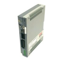
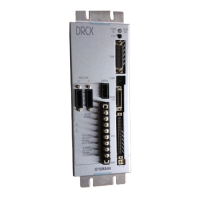
The I/O connector is used for connecting the ERCX controller to external equipment such as a PLC.
When using external equipment for I/O control, connect the wiring to the I/O connector supplied as
an accessory and then plug it into the I/O connector on the ERCX controller.
The signals assigned to each of the I/O connector terminals and their functions are described in detail
in Chapter 3.
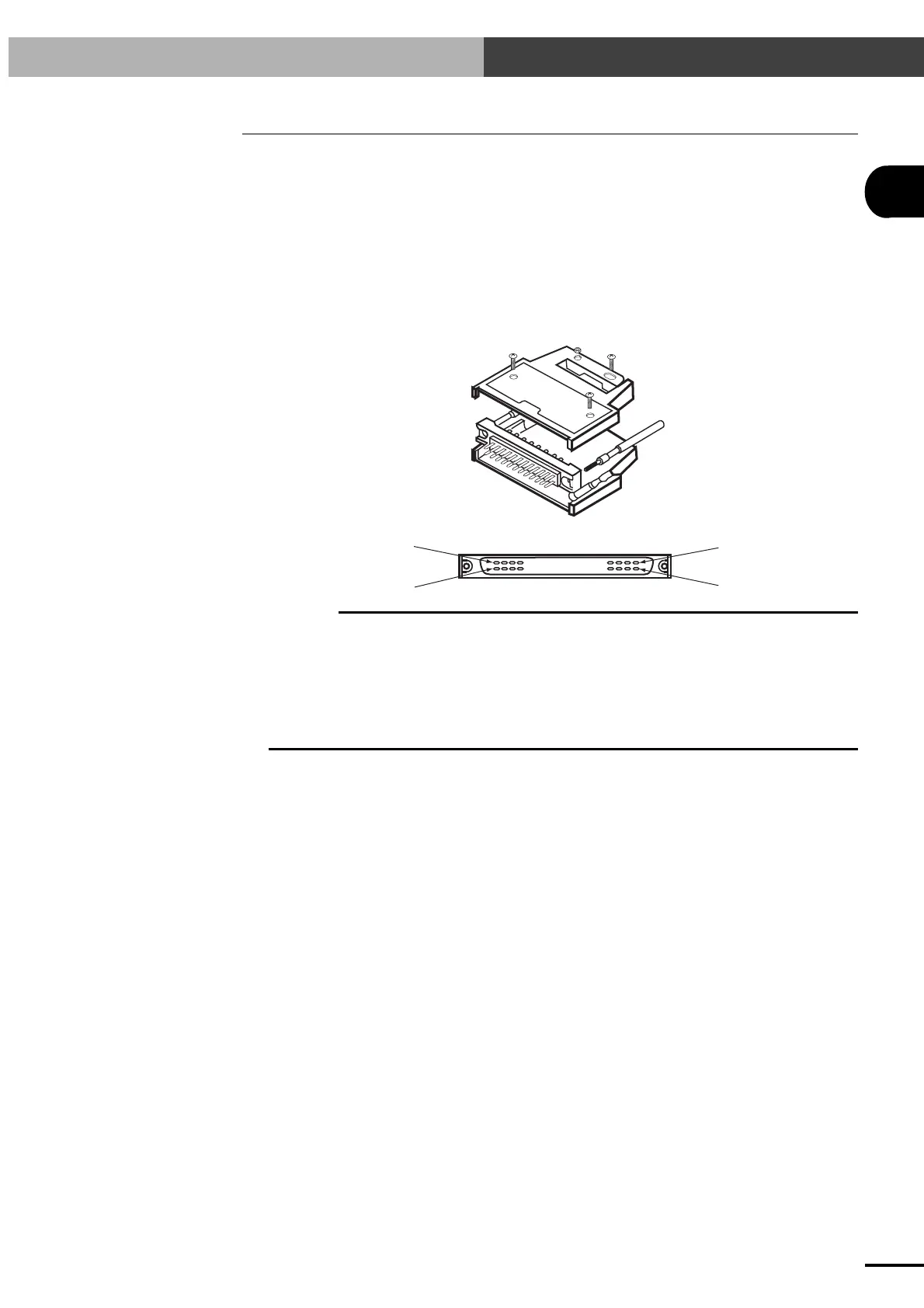
The I/O connector that is compatible with the ERCX controller is listed below.
Connector type No. : FCN-361P048-AU (Fujitsu)
Connector cover type No. : FCN-360C48-E
Row B, No. 1
Row A, No. 1
Row B
Row A
c
CAUTION
Even if not using I/O control, the I/O connector should be plugged in after completing the following wiring.
1. Short pin numbers A24 (EMG1) and B24 (EMG2).
2. Short pin numbers B4 (LOCK) and A15, B15(0V).
3. Connect pin numbers A13 and B13 (+IN, COM) to an external 24V power supply.
If step 1 is not completed, an emergency stop is triggered. If step 2 is not completed, an interlock occurs. In
either case, the controller cannot be operated (see Chapter 3).
Note that 24V power will not be supplied to the I/O circuit unless shorted as in 3. An alarm is issued (06:24V
POWER OFF) when power is not supplied and the operation disabled.
 Loading...