3-10
3
I/O INTERFACE
3-4 I/O Circuits
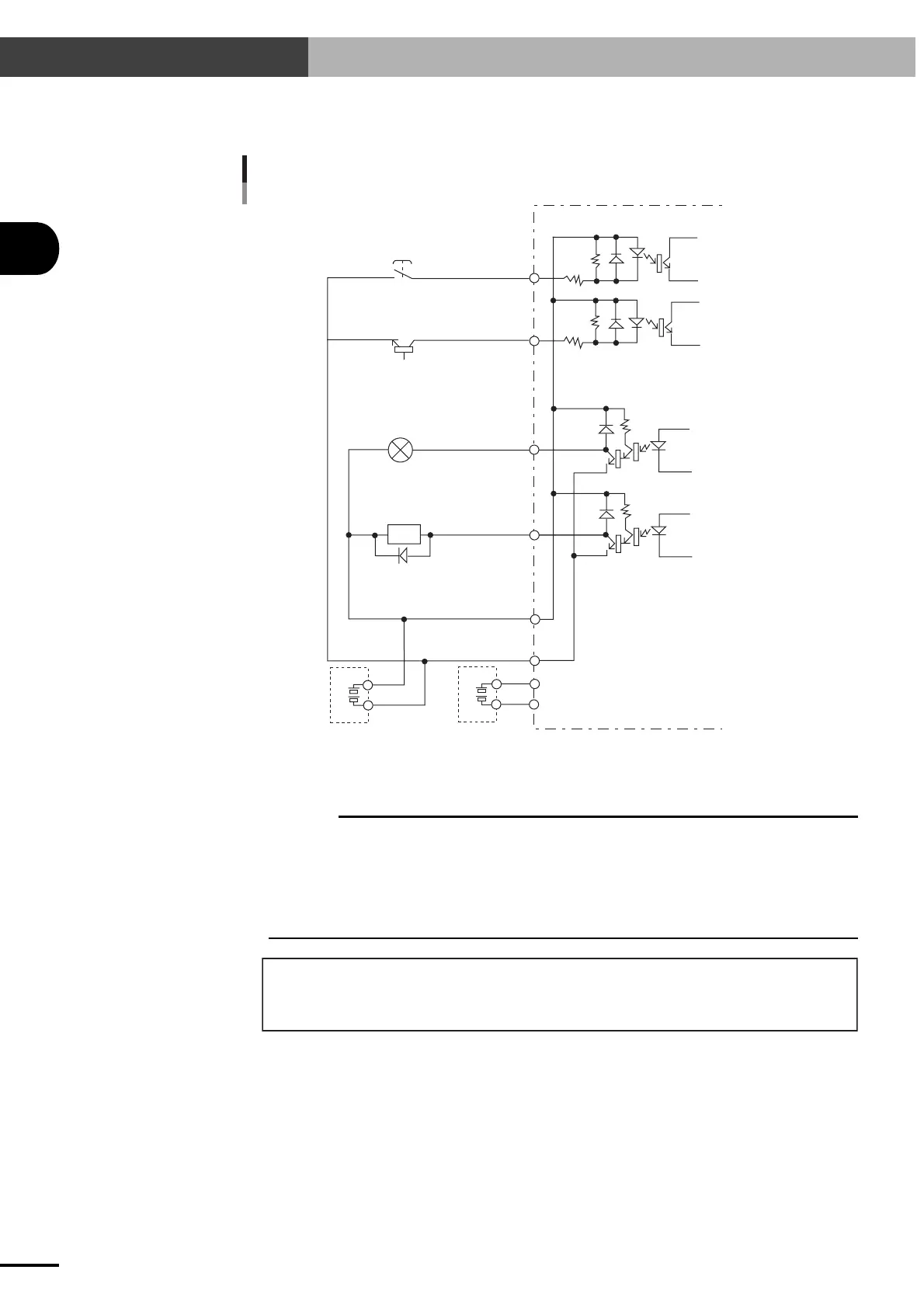
3-4-2 I/O circuit and connection example
When using a separate 24V power supply for I/O control
External 24V
power supply
for controller
Push-button
NPN transistor
Incandescent lamp
Solenoid valve
Input signal
Photocoupler
Output signal
DI
DO
DO
DI
+IN COM
0V
24V
N
Controller side
External 24V
power supply
for I/O control
c
CAUTION
Do not short the output terminal to the DC24V terminal. This may cause equipment breakdown.
When using an inductive load (such as a solenoid valve) as the output load, connect a high-speed diode as a
surge killer in parallel and near to the load to reduce noise.
When using a 2-wire type proximity sensor as an input signal, the residual voltage during on/off might exceed
the input range for the ERCX controller depending on the sensor type. Using such a sensor will cause erroneous
operation. Always check that the sensor meets the input signal specifications.
Keep the wires separated from the power lines of other machines, or shield the wires to prevent noise.
External 24V power supply for I/O control must have a capacity for:
Emergency stop circuit (0.05A) + I/O drive (depends on user application)
Additional power capacity (0.3A) for brake control is needed for robots with brake.
 Loading...