2-6
2
INSTALLATION AND CONNECTION
2-5 Connecting to the Robot
2-5 Connecting to the Robot
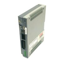
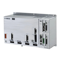
First make sure that the power to the ERCX controller is turned off, and then connect the robot cable
to the robot I/O connector on the front panel of the ERCX controller. Fully insert the robot I/O cable
until it clicks in position.
* When the robot cable is disconnected from the controller, an alarm (15: FEEDBACK ERROR
2) is issued. Since the controller is shipped with the robot cable disconnected, an alarm is
always issued when the controller is first turned on. But this is not an equipment problem.
2-5-1 Robot I/O connector and signal table
Mating connector type No. : 0-174046-2 (AMP)
Mating connector contact type No. : 0-175180-2
ERCX’s connector type No. : 0-174053-2
Signal table
Terminal No.
Signal name
Description
Terminal No.
Signal name
Description
1
2
3
4
5
6
7
8
9
10
11
12
13
14
15
16
BK1+
MW
MU
DG
WCK1+
R1+
PC1+
PS1+
BK1-
MV
FG
NC
WCK1-
R1-
PC1-
PS1-
Brake signal 1 (+)
Motor W-phase output
Motor U-phase output
Digital ground
Wire breakage detection 1 (+)
Resolver excitation output 1 (+)
Resolver COS input 1 (+)
Resolver SIN input 1 (+)
Brake signal 1 (-)
Motor V-phase output
Frame ground
No connection
Wire breakage detection 1 (-)
Resolver excitation output 1 (-)
Resolver COS input 1 (-)
Resolver SIN input 1 (-)
 Loading...