3-11
3
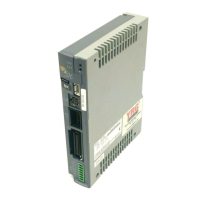
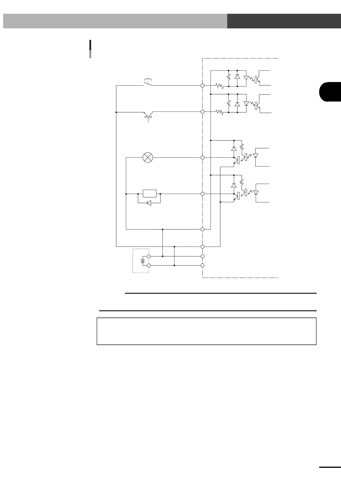
I/O INTERFACE
3-4 I/O Circuits
When shared with 24V power supply for controller
External 24V power supply
for I/O control and controller
Push-button
NPN transistor
Incandescent lamp
Solenoid valve
Input signal
Photocoupler
Output signal
DI
DO
DO
DI
+IN COM
0V
Controller side
24V
N
c
CAUTION
Select a 24V power supply with a sufficient capacity. If the power supply capacity is insufficient, the robot may
not operate normally resulting in an unexpected error or alarm.
External 24V power supply must have a capacity for:
Controller (3A) + Emergency stop circuit (0.05A) + I/O drive (depends on user application)
Additional power capacity (0.3A) for brake control is needed for robots with brake.
 Loading...