ABCDEFGH
1
2
3
4
5
6
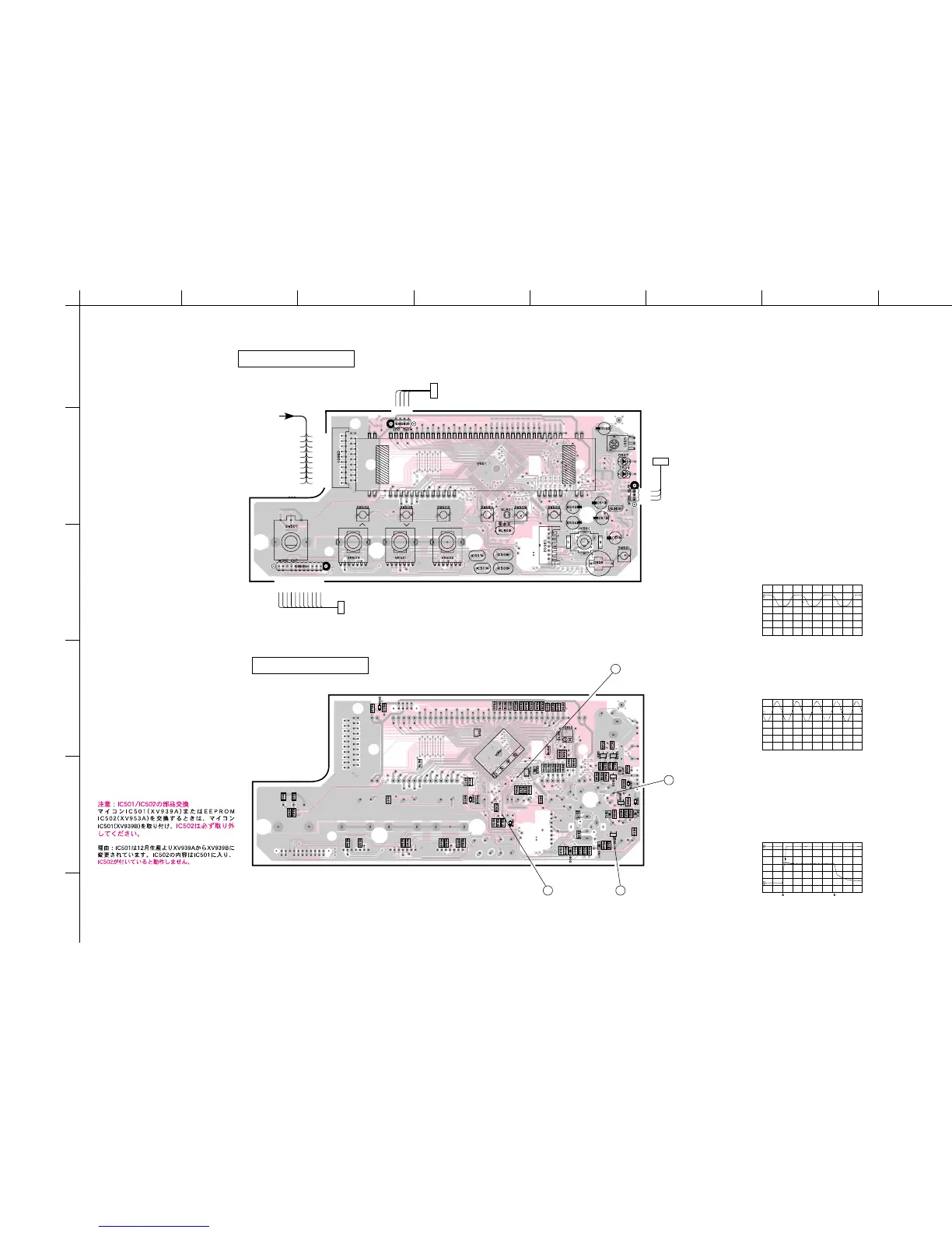
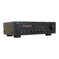
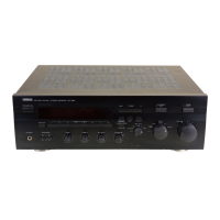
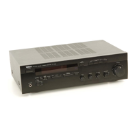
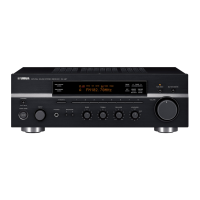
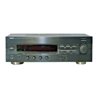
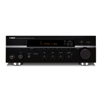
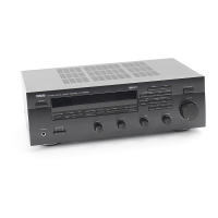
RX-E100
P. C. B. OPERATION (Lead Type Device View)
DG
TH
FAN-FE
FAN-DR
VOL-UP
RLY-SP
CE
DAT-I
MUT-A
STA
AUDIO
PRO-PS
DES
VOL-DN
SYS-I/O
PRO-I
CLK
DAT-O
MUT-T
STMO
FROM : MAIN (1)
F2
F1
G
—VP
TO : MAIN (4)
W503
#503
12S
PRY
DG
TO : MAIN (6)
W502
#502
T-IN-L
T-FB-L
E
T-FB-R
T-IN-R
T-OUT-L
E
T-OUT-R
E
HP-L
HP-R
TO : MAIN (1)
#501
W501
INPUT
PRESET/TUNING PRESET/BAND
AUTO/
MAN’L
MEMORY
DISPLAY
BASSTREBLEBALANCE
STANDBY/
ON
STANDBY
TIMER
P. C. B. OPERATION (Surface Mount Device View)
2 3
3
1
1
3
0
3
1
50
51
8
0
81
1
0
0
1
4
5
8
CH 2
CH 1
Point q (Pin 11 of IC501)
V : 2V/div, H : 10µsec/div
DC, 1 : 1 probe
0V
Point e
CH 1 : Collector of Q504
CH 2 : Collector of Q505
V : 2V/div (CH 1)
V : 5V/div (CH 2)
DC, 1 : 1 probe, H : 0.5sec/div
Point w (Pin 13 of IC501)
V : 2V/div, H : 50nsec/div
DC, 1 : 1 probe
0V
AC CORD : OFFAC CORD : ON
■ PRINTED CIRCUIT BOARD (Foil side)
E-19/J-17
0V
0V
CAUTION : For part replacement of IC501/IC502
When replacing the microprocessor IC501(XV939A) or
the EEPROM IC502(XV935A), install the
microprocessor IC501(XV939B) and
make sure to
remove the IC502.
Reason : The IC501 has been changed from XV939A to
XV939B starting with December production. As the new
IC501 contains the contents of the IC502, it will not
function if the IC502 is also installed.