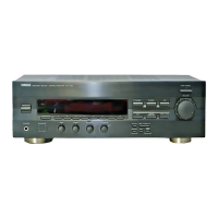
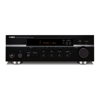
RX-E100
RX-E100
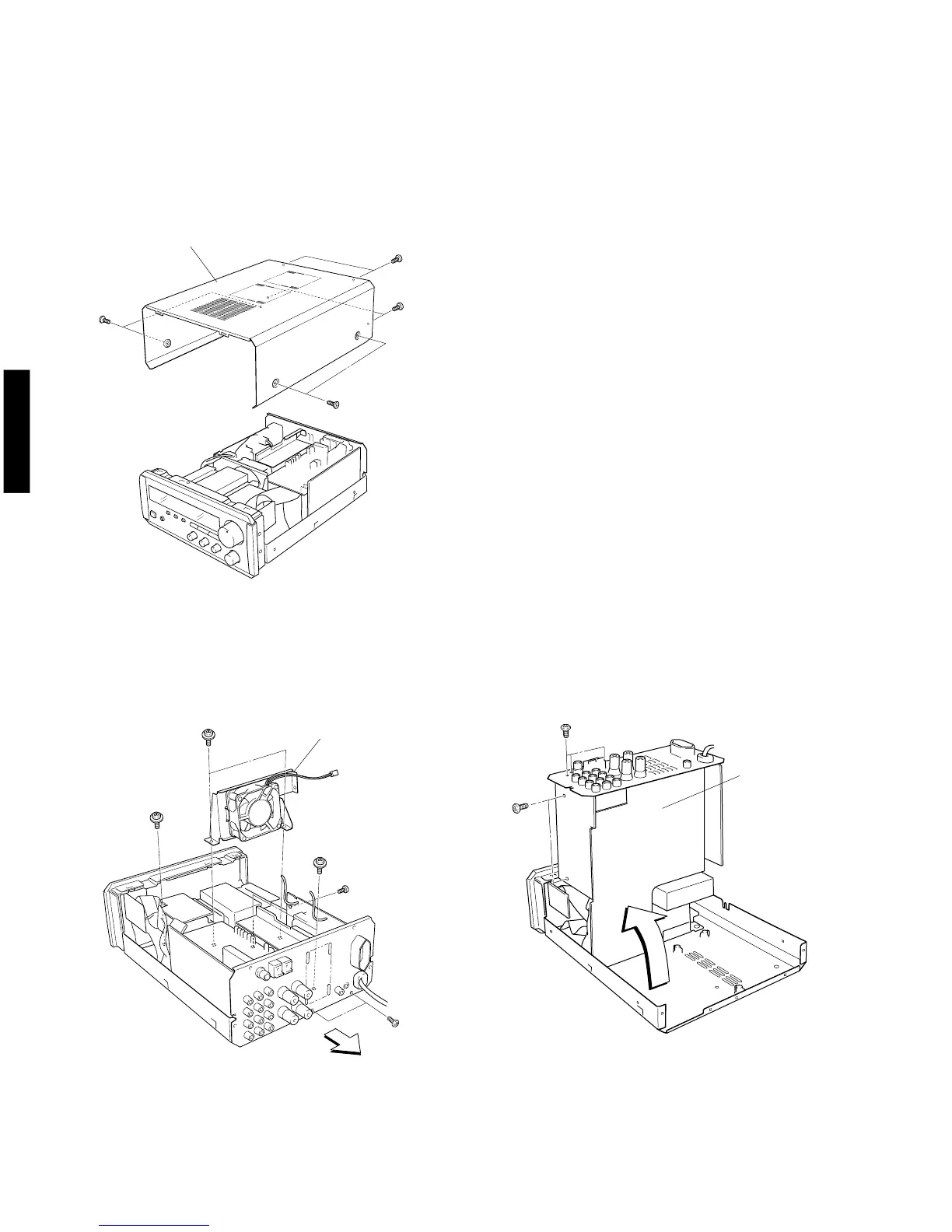
Fig. 1
q
q
Top Cover
Fan
w
w
e
r
t
Fig. 2
Amp Unit
y
Fig. 3
■ DISASSEMBLY PROCEDURES (Remove parts in disassembly order as numbered.)
1. Removal of Top Cover
a. Remove 4 screws ( q ) and 4 screws ( w ) in Fig.
1.
5
y
2. Checking the Amp Unit and replacing parts
a. Disconnect the power plug from AC outlet.
b. Remove 2 screws ( e ) attaching the rear panel to
the chassis. (Fig. 2)
c. Disconnect the connector for the fan.
d. Remove 3 screws ( r, t ) attaching the fan to
the chassis and then remove the fan. (Fig. 2)
e. Remove 3 screws ( y ) attaching the Main P.C.B.
to the Heat Sink. (Fig. 2)
f. Loosen the wiring harness.
g. Move the Amp Unit toward the rear. (Fig. 2)
h. As shown in Fig. 3, set the Amp Unit upright.
i. Fit insulating material (thick paper, etc.)to prevent
the chassis and the transformer from contacting the
Main P.C.B..
j. Using a wire, connect the pin jack ground to the
chassis.
(If they are left unconnected, the grounding remains
open and the unit fails.)
k. Connect the power plug and turn on the power
switch.
l. When replacing parts, remove 5 screws ( u, i )
fixing the P.C.B. Tuner and then remove the P.C.B.
Tuner. (Fig. 3)
u
i
(Copper)
(Copper)
(Copper)