ABCDEFGH
1
2
3
4
5
6
IJKL
7
8
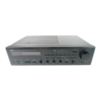
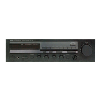
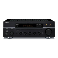
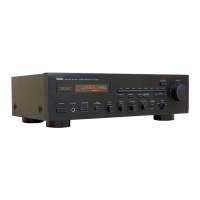
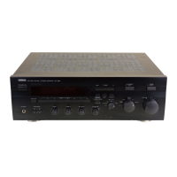
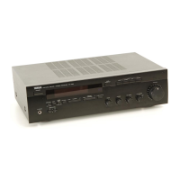
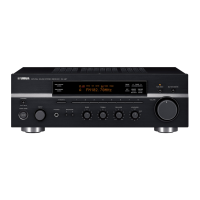
RX-E100
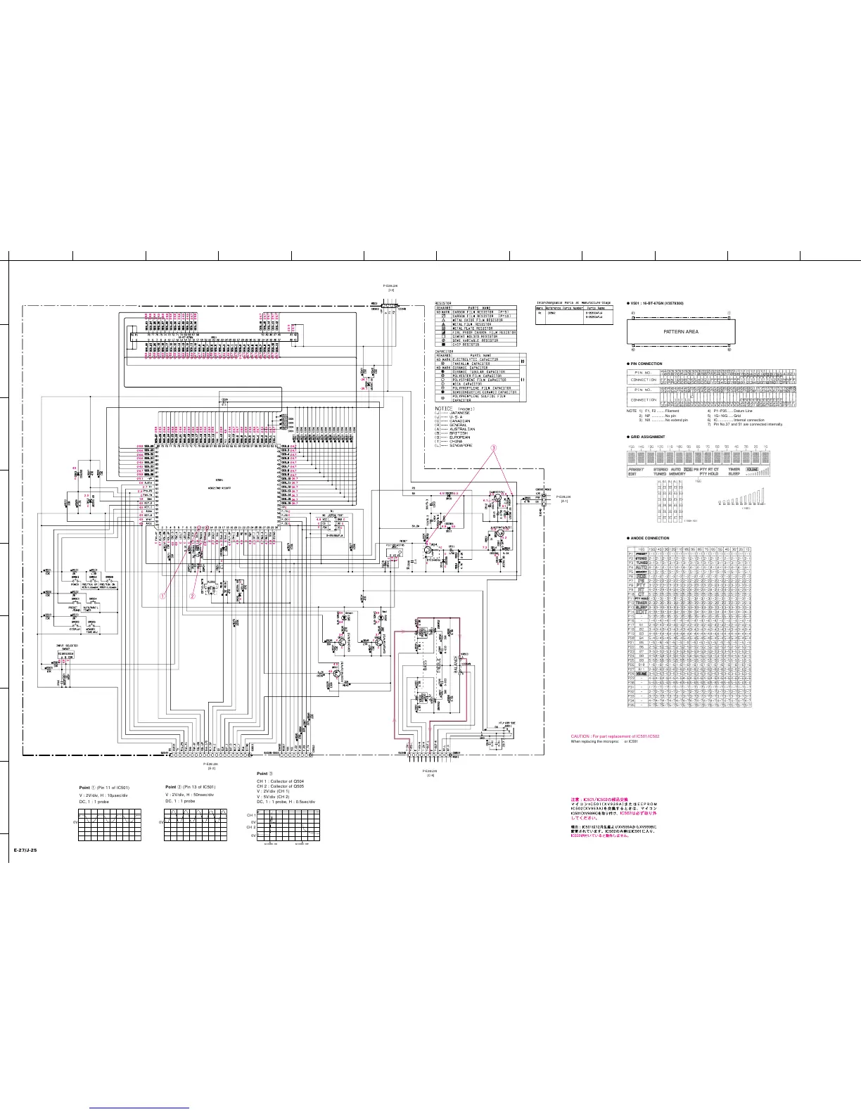
■ SCHEMATIC DIAGRAM (OPERATION)
* All voltage are measured with a 10MΩ/V DC electric volt meter.
* Components having special characteristics are marked Z and
must be replaced with parts having specifications equal to those
originally installed.
* Schematic diagram is subject to change without notice.
CPU
RESET
REGULATOR
-28.8
-28.8
-26.6
-24.5
-28.8
-28.8
-26.6
-26.6
-26.6
-24.5
-24.5
-26.7
-26.7
-26.7
-26.7
-26.7
-26.7
-23.9
-23.9
-24.1
-29.1
4.9 5.5
4.8 5.5
5.5
6.1
11.9
6.1
0
11.9
7.3
4.7
0
4.9
4.9
0
4.9
3.7
4.9
3.4
3.4
0
0
0
0
4.9
0
4.5
3.7
0
0
0
6.7
0
11.9
11.2
-28.8
-28.8
-26.7
-26.7
-26.7
-26.7
-26.7
-26.7
-26.7
-26.7
-28.8
-24.5
-26.6
-28.8
-28.8
-28.8
-24.6
-26.6
-28.9
-28.9
-28.9
-24.6
-26.6
-28.9
-28.9
0
-28.9
4.8
-24.6
-26.7
-26.7
-28.9
-28.9
-24.6
-28.9
-26.7
-24.5
-24.5
-26.7
-26.7
0
4.7
0
0
4.9
4.9
0
0
0
1.1
1.6
4.7
2.3
0
2.1
4.8
0
0
0
0
4.7
0
4.9
4.9
0
4.8
0.1
0
4.7
4.7
3.8
4.8
-26.7
-26.7
-26.7
-26.7
-26.7
-26.7
-26.7
0
0
0
0
0
-28.8
-26.6
-26.6
-26.6
-24.5
-24.5
-26.7
-28.8
-29.1
4.9
0
2.5
0
0
4.9
4.9
0
0
0.6
2.7
2.5
0
1.8
4.9
4.9
0
4.9
4.9
4.9
-24.6
-24.6
-26.6
-28.9
-28.9
-28.9
-24.6
-24.5
-24.5
-26.6
-28.9
-28.9
-28.9
-28.9
-28.9
-28.9
-24.6
-26.7
-26.7
-26.7
-26.7
-26.7
-26.7
-26.7
-26.7
-26.7
-26.7
-26.7
-26.7
-26.7
-26.7
-26.7
w
q
e
0
4.8
0
0
0
0
CH 2
CH 1
Point q (Pin 11 of IC501)
V : 2V/div, H : 10µsec/div
DC, 1 : 1 probe
0V
Point e
CH 1 : Collector of Q504
CH 2 : Collector of Q505
V : 2V/div (CH 1)
V : 5V/div (CH 2)
DC, 1 : 1 probe, H : 0.5sec/div
Point w (Pin 13 of IC501)
V : 2V/div, H : 50nsec/div
DC, 1 : 1 probe
0V
AC CORD : OFFAC CORD : ON
E-27/J-25
P-E28/J26
[E-2]
P-E28/J26
[C-8]
P-E28/J26
[A-1]
P-E28/J26
[I-2]
● V501 : 16-BT-67GN (V3579300)
● PIN CONNECTION
NOTE 1) F1, F2 ........Filament
2) NP .............No pin
3) NX .............No extend pin
● GRID ASSIGNMENT
● ANODE CONNECTION
4) P1~P35 ...... Datum Line
5) 1G~16G .....Grid
6) IC ...............Internal connection
7) Pin No.37 and 51 are connected internally.
0V
0V
CAUTION : For part replacement of IC501/IC502
When replacing the microprocessor IC501(XV939A) or
the EEPROM IC502(XV935A), install the
microprocessor IC501(XV939B) and
make sure to
remove the IC502.
Reason : The IC501 has been changed from XV939A to
XV939B starting with December production. As the new
IC501 contains the contents of the IC502, it will not
function if the IC502 is also installed.