8
S80
DISASSEMBLY PROCEDURE
[300] [300]
[42]
[42]
[96]
[42]
[210] [200] [210]
PN
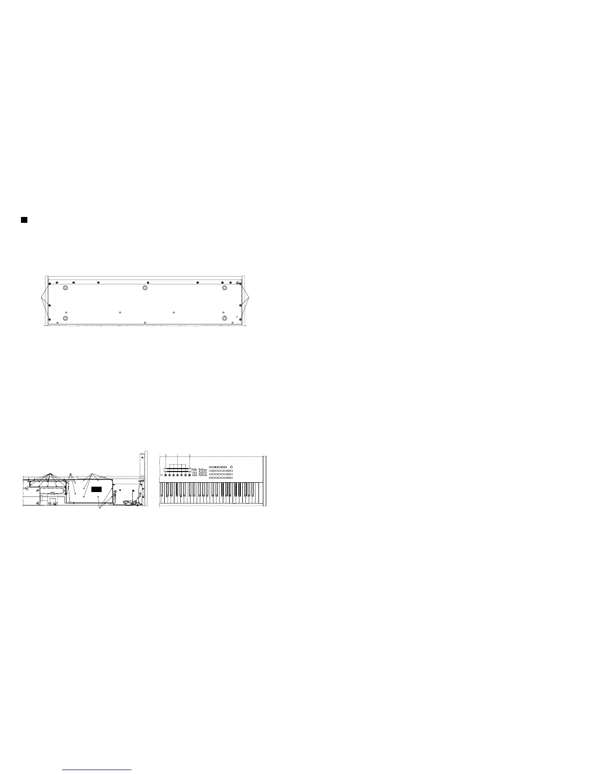
[300]: Bind Head Screw 5.0X20 MFZN2BL (VB857600)
Fig.1
1. Remove the six (6) screws marked [300] from the
bottom of the main unit and open the control panel
assembly by lifting it up. (Fig. 1)
[42]: Bind Head Tapping Screw-B 3.0X6 MFZN2BL (EP600230)
[96]: Bind Head Tapping Screw-B 3.0X6 MFZN2BL (EP600230)
Fig.2
2. PN Circuit Board
2-1 Open the control panel assembly. (See procedure 1.)
2-2 Remove the twelve (12) screws marked [42]. The
PN circuit board can then be removed. (Fig. 2)
3. RV Circuit Board
3-1 Open the control panel assembly. (See procedure 1.)
3-2 Remove the five (5) knobs marked [200] and the
two (2) knobs marked [210] from the panel surface.
3-3 Remove the ten (10) screws marked [96]. The RV
circuit board can then be removed. (Fig. 2)
4. Power Supply Unit
4-1 Open the control panel assembly. (See procedure 1.)
4-2 Remove the two (2) screws marked [30] and the
five (5) screws marked [31]. (Fig. 3)
4-3 Remove the four (4) screws marked [22] from the
power assembly. (Fig. 3) Power supply unit can then
be removed.
5. SM Circuit Board
5-1 Open the control panel assembly. (See procedure 1.)
5-2 Remove the two (2) screws marked [96]. The SM
circuit board can then be removed. (Fig. 4)
6. SV Circuit Board
6-1 Open the control panel assembly. (See procedure 1.)
6-2 Remove the three (3) screws marked [130]. The PLG
angle can then be removed. (Fig. 4)
6-3 Remove the five (5) knobs marked [220] from the
panel surface. (Fig. 4)
6-4 Remove the six (6) screws marked [82]. The SV
circuit board can then be removed. (Fig. 3)
7. Display Assembly
7-1 Open the control panel assembly. (See procedure 1.)
7-2 Remove the PLG angle. (See procedure 6-2.)
7-3 Remove the four (4) screws marked [92]. The display
assembly can then be removed. (Fig. 3)
8. JK Circuit Board
8-1 Open the control panel assembly. (See procedure 1.)
8-2 Remove the nine (9) screws marked [81]. The JK
circuit board can then be removed. (Fig. 3)
〈
BOTTOM VIEW
〉
〈
BOTTOM VIEW
〉
〈
TOP VIEW
〉
 Loading...