Frame, suspension and final drive 6*27
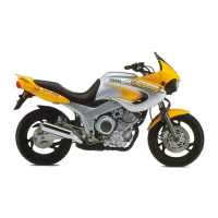
14.8 Swingarm bearing (1) and bush (2) installed depth
A 4 mm B 8 mm
in the Reference section for details of using a
drawbolt tool or bearing extractor with slide-
hammer attachment to remove the bearings and
bushes and install new ones. When installing the
new components note that they must be
positioned to a specific depth in the swingarm
housings (see illustration).
9 Measure the length of each bearing spacer
and the thickness of each washer and
compare them to the specifications, renewing
any component that is worn. Note: Worn
components will increase swingarm sidepiay.
10 Although it is possible to measure the
swingarm sidepiay with all components
assembled on the bike it is preferably to
calculate sidepiay by direct measurement of
the individual components. Done this way,
you will be able to install any shims required
as the swingarm is refitted. You will need a
vernier gauge to do this accurately. Measure
the width of the swingarm mounting boss on
the engine and call this dimension A. Record
the lengths of the two spacers measured in
Step 9 as dimensions B and C. Now measure
the overall length of the swingarm (from the
outside of one bearing housing to the outside
of the other) and record this as dimension D.
Record the thicknesses of the two washers
(added together) measured in Step 9 and
record this as dimension E. Compute
swingarm sidepiay by subtracting the
swingarm width and washer thicknesses from
the boss width and spacer lengths, thus:
Sidepiay = (A + B + C) - (D + E)
If the sidepiay is within the limit of 0.4 to 0.7 mm
no shims are required. If sidepiay exceeds 0.7
mm, fit one or two shims as required to bring
sidepiay within the specified limit. Shims are
available in 0.3 mm thicknesses. The shims
should be fitted between the cap and washer; if
two shims are required fit one on each side,
whereas if only one shim is required fit this on
the right-hand side.
11 Press the grease seals into their locations
in each side of the swingarm bearing
housings, renewing them if they are damaged or
deteriorated.
12 Lubricate the bearings, bushes and spacers
with lithium-based grease. Do not forget to install
the bearing spacer between the bearings in the
swingarm. Install the washers, shims (where
fitted) and caps on the outer ends of the
swingarm.
15 Drive chain - removal,
cleaning and installation
Endless type chain
Note: An endless chain has no riveted (soft) link -
all links and pins are the same. The chain fitted as
original equipment and supplied as a spare part
from Yamaha dealers is of the endless type.
Warning: NEVER install a drive
chain which uses a clip-type master
(split) link.
Removal
1 Remove the swingarm (see Section 13). Note
that if the front sprocket is being removed, the
sprocket nut should be slackened before
removing the swingarm, so that the rear brake
can be used so stop the sprocket turning (see
Section 16).
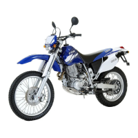
2 On TDM and XTZ models, unscrew the bolts
securing the outer front sprocket cover and
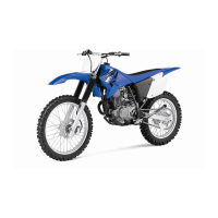
remove the cover (see illustration). Unscrew the
gearchange lever linkage arm pinchbolt and
remove the arm from the shaft, noting the
alignment of the punch mark with the slit in the
clamp (see illustration). If no mark is visible,
make your own before removing the arm so that
it can be correctly aligned with the shaft on
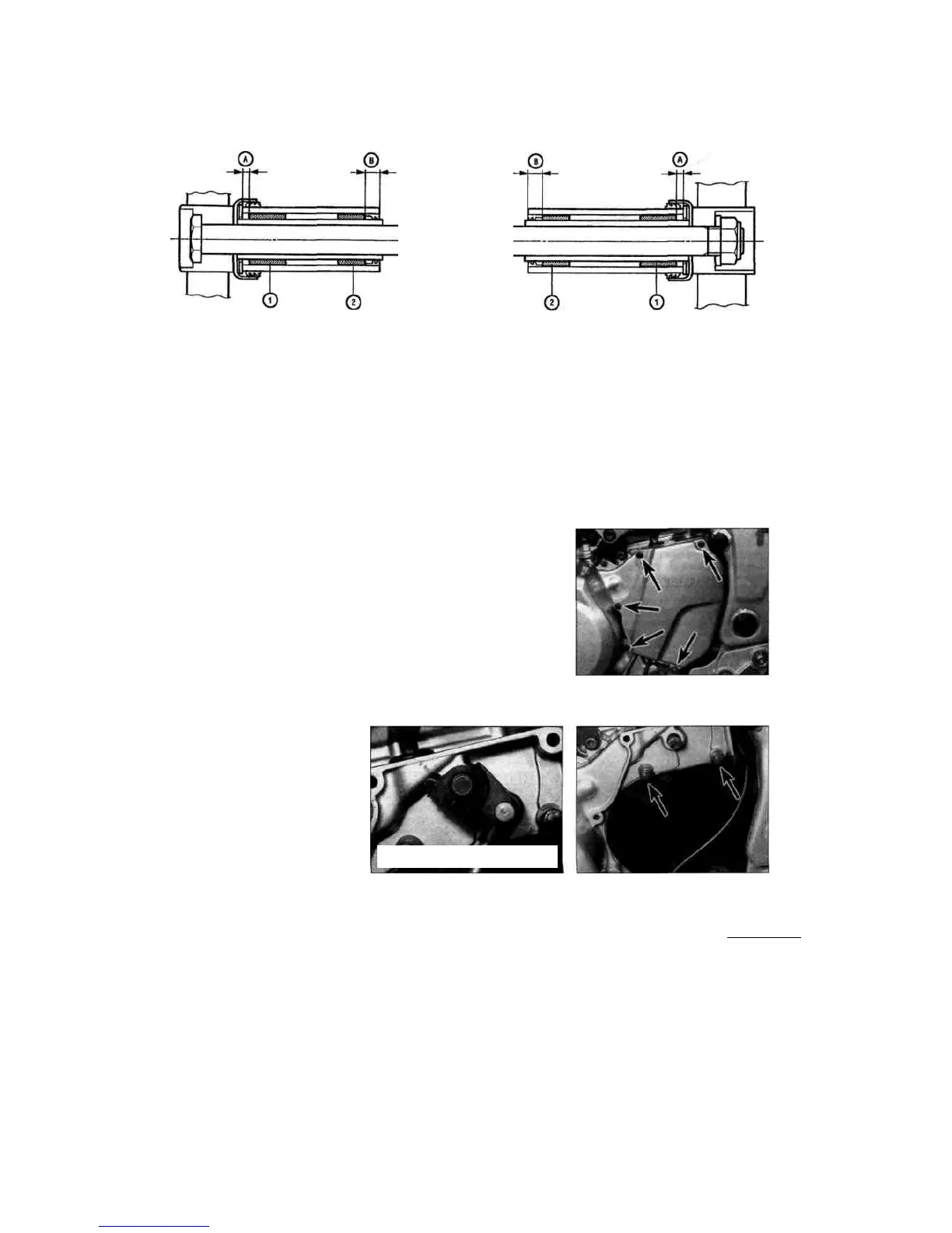
installation. Unscrew the bolts securing the inner
sprocket cover, on TDM models noting the clip
secured by the top rear bolt, and remove the
cover (see illustration).
3 On TRX models, unscrew the gearchange
15.2a Unscrew the bolts (arrowed) and
remove the cover
15.2c Unscrew the bolts (arrowed) and
remove the inner cover
6
Staned by Stalker

 Loading...