2»20 Engine, clutch and transmission
10.18a Use new sealing washers on each
side of the union ...
the union, and tighten the banjo bolt to the
specified torque (see illustrations).
19 If removed, fit the vacuum hose(s) onto the
inlet manifold(s) and fit the clamp(s).
20 Install the remaining components in a
reverse of their removal sequence, referring to
the relevant Sections or Chapters (see Steps 1, 2
and 3).
11 Valves/valve seats/valve
guides - overhaul
1 Because of the complex nature of this
job and the special tools and equipment required,
most owners leave servicing of the valves, valve
seats and valve guides to a professional.
2 The home mechanic can, however, remove
the valves from the cylinder head, clean and
check the components for wear and assess the
extent of the work needed, and, unless a valve
overhaul is required, grind in the valves (see
Section 12).
3 The engineer will renew the valves, guides
and springs, recut the valve seats, clean and
polish the valve ports and reassemble the valve
components.
4 After the valve overhaul has been performed,
the head will be in like-new condition. When the
head is returned, be sure to clean it again very
thoroughly before installation on the engine to
remove any metal particles or abrasive grit that
may still be present from the valve service
operations.
10.18b ... and tighten the banjo bolt to the
specified torque
Use compressed air, if available, to blow out all
the holes and passages.
12 Cylinder head and valves -
disassembly, inspection and
reassembly
1 As mentioned in the previous section,
valve overhaul should be left to an engineer.
However, disassembly, cleaning and inspection
of the valves and related components can be
done (if the necessary special tools are
available) by the home mechanic. This way no
expense is incurred if the inspection reveals that
overhaul is not required at this time.
2 To disassemble the valve components without
the risk of damaging them, a valve spring
compressor is absolutely essential. Make sure
that it is suitable for motorcycle work.
Disassembly
3 Before proceeding, arrange to label and store
the valves along with their related components
in such a way that they can be returned to their
original locations without getting mixed up (see
illustration). A good way to do this is to use the
same container as the shims are stored in (see
Section 8), or to obtain a separate container
which is divided into ten compartments, and to
label each compartment with the identity of the
valve which will be stored in it (ie number of
cylinder, inlet or exhaust side, inner, middle or
outer valve). Alternatively, labelled plastic bags
will do just as well.
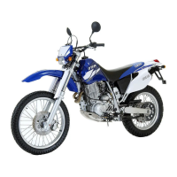
12.3 Valve components
1 Collets 5 Valve stem oil
2 Spring retainer seal
3 Valve spring 6 Valve
4 Spring seat
4 Clean all traces of old gasket material from the
cylinder head. If a scraper is used, take care not
to scratch or gouge the soft aluminium.
Refer to Tools and Workshop
Tips in the Reference section for
details of gasket removal
methods.
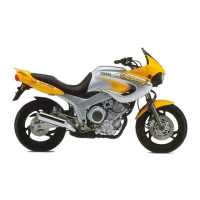
5 Compress the valve spring on the
first valve with the spring compressor, making
sure it is correctly located onto each end of the
valve assembly (see illustration). Do not
compress the spring any more than is absolutely
necessary. Remove the collets, using either
needle-nose pliers, tweezers, a magnet or a
screwdriver with a dab of grease on it (see
illustration). Carefully release the valve spring
compressor and remove the spring retainer,
noting which way up it fits, the spring, the spring
seat, and the valve, from the head (see
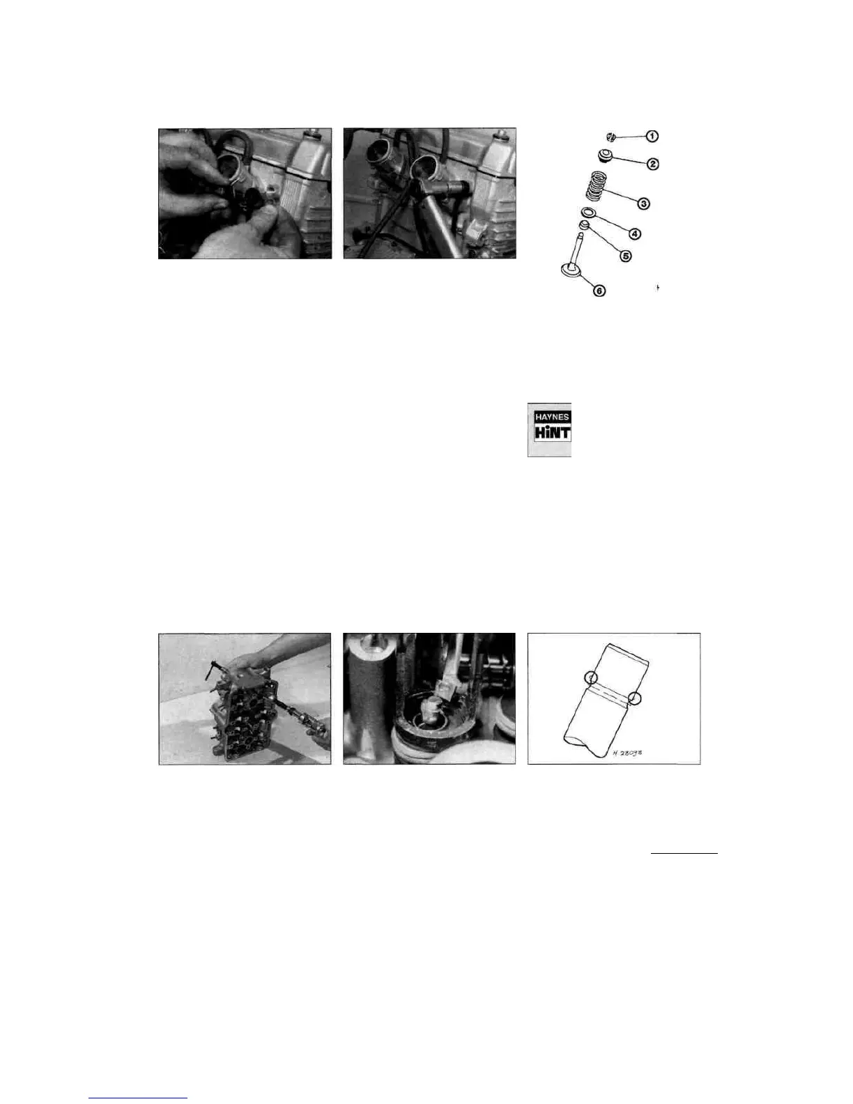
illustration 12.3). If the valve binds in the guide
(won't pull through), push it back into the head
and deburr the area around the collet groove with
a very fine file or whetstone (see illustration).
12.5a Compressing the valve springs
using a valve spring compressor
12.5b Remove the collets with needle-
nose pliers, tweezers, a magnet or a
screwdriver with a dab of grease on it
12.5c If the valve stem won't pull through
the guide, deburr the area above the collet
groove
Staned by Stalker

 Loading...