15.9a Install the oil ring expander in its
groove...
around the piston while pushing the rail into the
groove. Next, install the lower side rail in the
same manner (see illustrations). Make sure the
ends of the expander do not overlap.
10 After the three oil ring components have
been installed, check to make sure that both the
upper and lower side rails can be turned
smoothly in the ring groove.
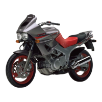
11 The upper surface of each compression ring
is marked with a mark or letter at one end (see
illustration). Make sure that the identification
mark or letter near the end gap is facing up when
installed.
12 Fit the second ring into the middle groove in
the piston. Make sure the identification letter
near the end gap is facing up. Do not expand the
ring any more than is necessary to slide it into
place. To avoid breaking the ring, use a piston
ring installation tool.
13 Finally, install the top ring in the same
manner into the top groove in the piston. Make
sure the identification letter near the end gap is
facing up.
14 Once the rings are correctly installed, check
they move freely without snagging and stagger
their end gaps as shown (see illustration).
15.9b ... and fit the side rails each side of it.
The oil ring must be installed by hand
16 Clutch - removal, inspection
lfe>
and installation
Note: The clutch can be removed with the
engine in the frame. If the engine has been
removed, ignore the steps which don't apply.
Removal
1 Drain the engine oil (see Chapter 1).
2 Detach the clutch cable from the operating
lever on the clutch cover (see Section 17).
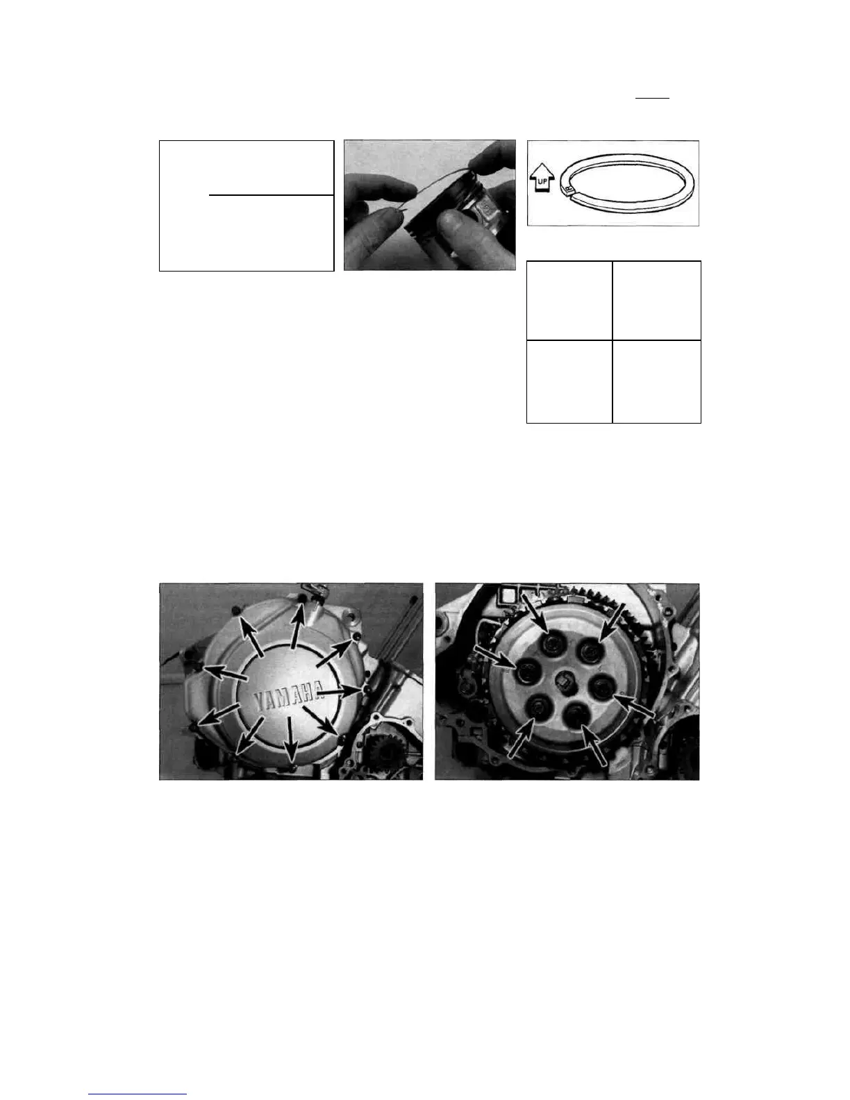
3 Working evenly in a criss-cross pattern,
unscrew the clutch cover bolts (see illustration).
Lift the cover away from the engine, being
prepared to catch any residual oil which may be
released as the cover is removed.
4 Remove the gasket and discard it. Note the
positions of the two locating dowels fitted to the
crankcase and remove them for safekeeping if
they are loose.
5 Working in a criss-cross pattern, gradually
slacken the clutch pressure plate bolts
15.11 Compression ring top surface is
marked by a letter
15.14 Stagger the ring end gaps as shown
1 Top ring
2 Oil ring lower rail
3 Oil ring upper rail
4 Second (middle) ring
until spring pressure is released (see
illustration). Counter-hold the clutch housing to
prevent it turning. Remove the bolts and springs,
then lift out the clutch pressure plate complete
with its pull rod, thrust bearing and plate washer
(see illustrations 16.30b and a). 6 Grasp the
complete set of clutch plates and
16.3 Unscrew the clutch cover bolts (arrowed) and remove the
cover
16.5 Clutch pressure plate bolts (arrowed)
Scaned by Stalker
 Loading...