4-18
CYLINDER HEAD, CYLINDER AND PISTON
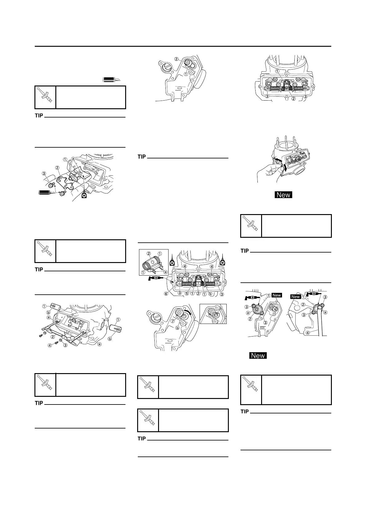
INSTALLING THE POWER VALVE
1. Install:
• Power valve 1 "1"
• Valve holder 2 "2"
• Bolt (valve holder 2) "3"
• Install the power valve 1 with its
gouge "a" facing upside.
• Apply the molybdenum disulfide oil
on the power valve 1.
2. Install:
• Power valve 2 "1"
• Link rod "2"
• Washer "3"
• Screw (link rod) "4"
Install the link rod with the cuts "a" in
its arm ends fitting over the pins "b"
on the power valves 2.
3. Install:
• Thrust plate "1"
• Screw (thrust plate) "2"
Be sure to install the thrust plate to
the cylinder before installing the valve
shaft.
4. Check:
• Spring 1 "1"
• Link lever "2"
• Pulley "3"
• Spring 2 "4"
• Washer "5"
• Valve shaft "6"
• Install the spring 1 to the link lever,
and then to the cylinder.
• Install the spring 1 with its stopper
portion "a" facing inward.
• Apply the molybdenum disulfide oil
on the grooves in the pulleys.
• Apply the lithium soap base grease
on the oil seal lip.
• Install the valve shaft with its cut "b"
aligning with the thrust plate "7",
and then rotate the valve shaft so
that its cut faces upward.
5. Install:
• Valve holder 1 "1"
• Bolt (link lever) "2"
• Bolt (pulley) "3"
First tighten the bolt (link lever), and
then tighten the bolts (pulleys).
6. Check:
• Power valve 1 smooth movement
Unsmooth movement→Repair or
replace.
7. Install:
• O-ring "1"
• Side holder "2"
• Screw (side holder) "3"
• YPVS breather hose "4"
• Apply the lithium soap base grease
on the O-rings.
• Install the side holder with its pro-
jection "a" facing upward.
8. Install:
• Gasket (power valve cover) "1"
• Power valve cover "2"
• Screw (power valve cover) "3"
• Install the gasket with its cut "a" fac-
ing downward and the seal print
side toward the power valve cover.
• Install the power valve cover so that
the arrow mark "b" faces upward.
Bolt (valve holder 2)
6 Nm (0.6 m•kg, 4.3
ft•lb)
Screw (link rod):
6 Nm (0.6 m•kg, 4.3
ft•lb)
Screw (thrust plate):
6 Nm (0.6 m•kg, 4.3
ft•lb)
Bolt (link lever):
4 Nm (0.4 m•kg, 2.9
ft•lb)
Bolt (pulley):
4 Nm (0.4 m•kg, 2.9
ft•lb)
Screw (side holder):
4 Nm (0.4 m•kg, 2.9
ft•lb)
Screw (power valve cov-
er):
4 Nm (0.4 m•kg, 2.9
ft•lb)
 Loading...