102
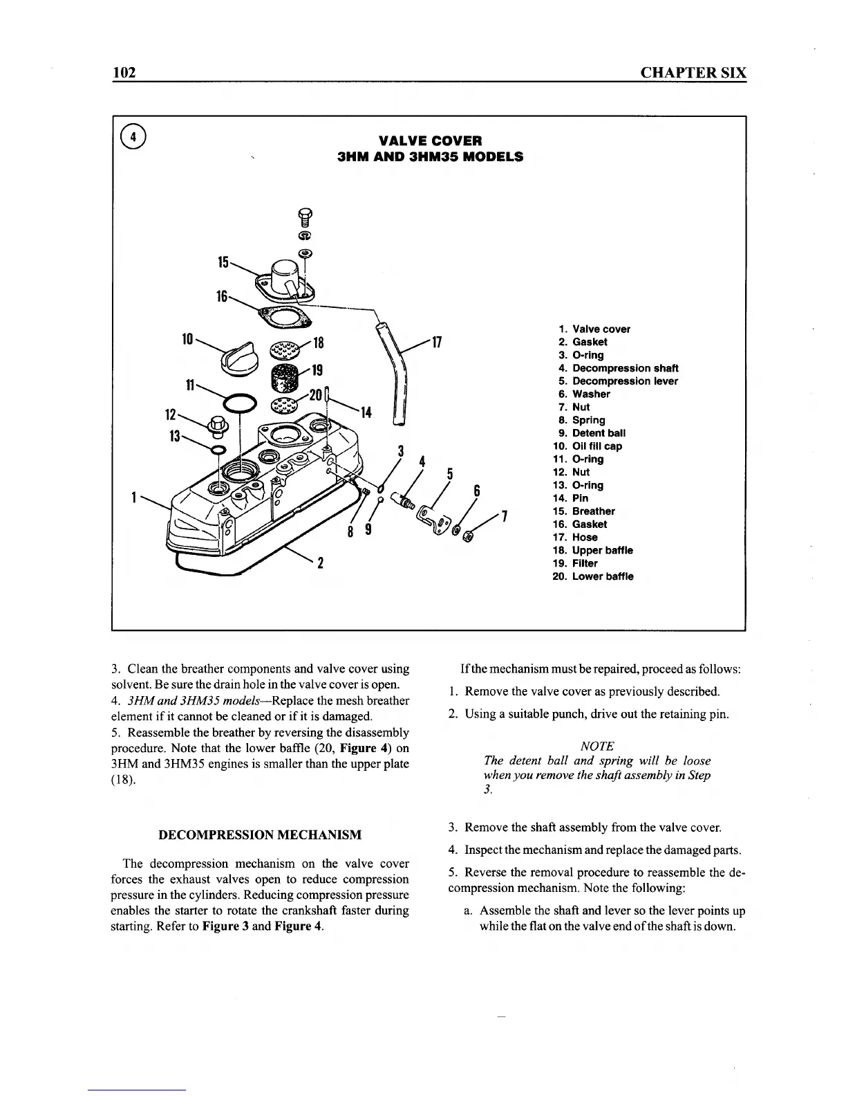
VALVE
COVER
3HM
AND
3HM35
MODELS
CHAPTER
SIX
1. Valve cover
2. Gasket
3.
a-ring
4. Decompression shaft
5. Decompression lever
6. Washer
7. Nut
8. Spring
9. Detent ball
10. Oil fill cap
11.
a-ring
12. Nut
13.
a-ring
14. Pin
15. Breather
16. Gasket
17. Hose
18. Upper baffle
19. Filter
20. Lower baffle
3. Clean the breather components and valve cover using
solvent. Be sure the drain hole in the valve cover is open.
4.
3HM
and 3HM35 models-Replace the mesh breather
element
if
it cannot be cleaned or
if
it is damaged.
5. Reassemble the breather by reversing the disassembly
procedure. Note that the lower baffle (20, Figure 4) on
3HM and 3HM35 engines is smaller than the upper plate
(18).
DECOMPRESSION MECHANISM
The decompression mechanism on the valve cover
forces the exhaust valves open to reduce compression
pressure in the cylinders. Reducing compression pressure
enables the starter to rotate the crankshaft faster during
starting. Refer to
Figure
3 and Figure 4.
Ifthemechanism must be repaired, proceed as follows:
1. Remove the valve cover as previously described.
2. Using a suitable punch, drive out the retaining pin.
NOTE
The detent ball and spring will be loose
when you remove the shaft assembly
in Step
3.
3. Remove the shaft assembly from the valve cover.
4. Inspect the mechanism and replace the damaged parts.
5. Reverse the removal procedure to reassemble the de-
compression mechanism. Note the following:
a. Assemble the shaft and lever so the lever points up
while the flat on the valve end
of
the shaft is down.