MULTI
CYLINDER
ENGINES
o
EXHAUST
MANIFOLD
103
2GM
AND
2GM20
MODELS
3GM,
3GM30,
3HM
AND
3HM35
MODELS
EXHAUST
MANIFOLD
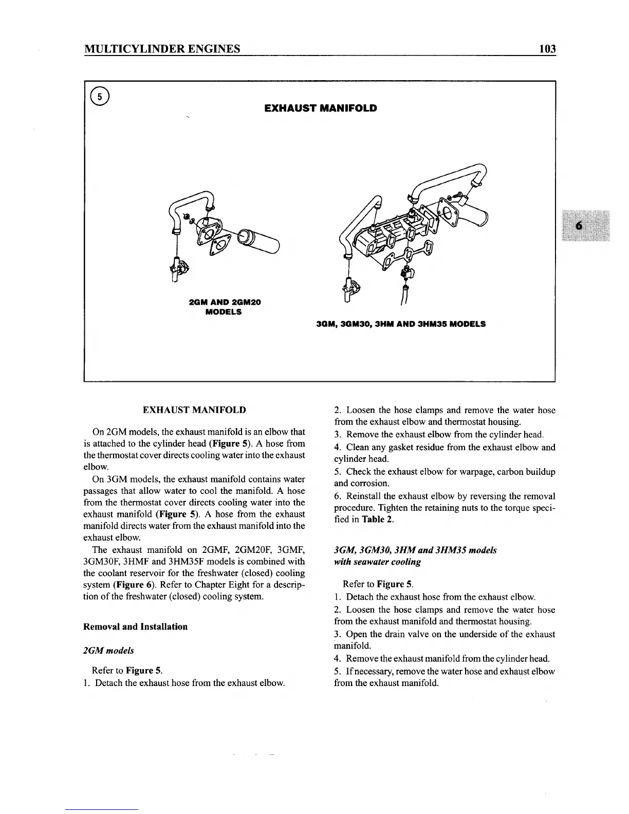
On 2GM models, the exhaust manifold is an elbow that
is attached to the cylinder head
(Figure 5). A hose from
the thermostat cover directs coolingwater into the exhaust
elbow.
On 3GM models, the exhaust manifold contains water
passages that allow water to cool the manifold.
A hose
from the thermostat cover directs cooling water into the
exhaust manifold
(Figure 5). A hose from the exhaust
manifold directs water from the exhaust manifold into the
exhaust elbow.
The exhaust manifold on 2GMF, 2GM20F, 3GMF,
3GM30F, 3HMF and 3HM35F models is combined with
the coolant reservoir for the freshwater (closed) cooling
system
(Figure 6). Refer to Chapter Eight for a descrip-
tion
of
the freshwater (closed) cooling system.
Removal and Installation
2GMmodeis
Refer to Figure 5.
1. Detach the exhaust hose from the exhaust elbow.
2. Loosen the hose clamps and remove the water hose
from the exhaust elbow and thermostat housing.
3. Remove the exhaust elbow from the cylinder head.
4. Clean any gasket residue from the exhaust elbow and
cylinder head.
5. Check the exhaust elbow for warpage, carbon buildup
and corrosion.
6. Reinstall the exhaust elbow by reversing the removal
procedure. Tighten the retaining nuts to the torque speci-
fied in
Table 2.
3GM, 3GM30,
3HM
and 3HM35 models
with seawater cooling
Refer to Figure 5.
1. Detach the exhaust hose from the exhaust elbow.
2. Loosen the hose clamps and remove the water hose
from the exhaust manifold and thermostat housing.
3. Open the drain valve on the underside
of
the exhaust
manifold.
4. Remove the exhaust manifold from the cylinderhead.
5. Ifnecessary, remove the water hose and exhaust elbow
from the exhaust manifold.