MUL
TIC
YLIN DER
ENG
INES
8
A
127
Inter-mediate
'l
ain Bearing
6
Width
I. Remove the intermediate bearing housing bolts
(Fi~
ure 68).
2. Separate the intermediate bearing housing halves from
the crank shaft.
3. Inspect the bearings for excessive wear and damage.
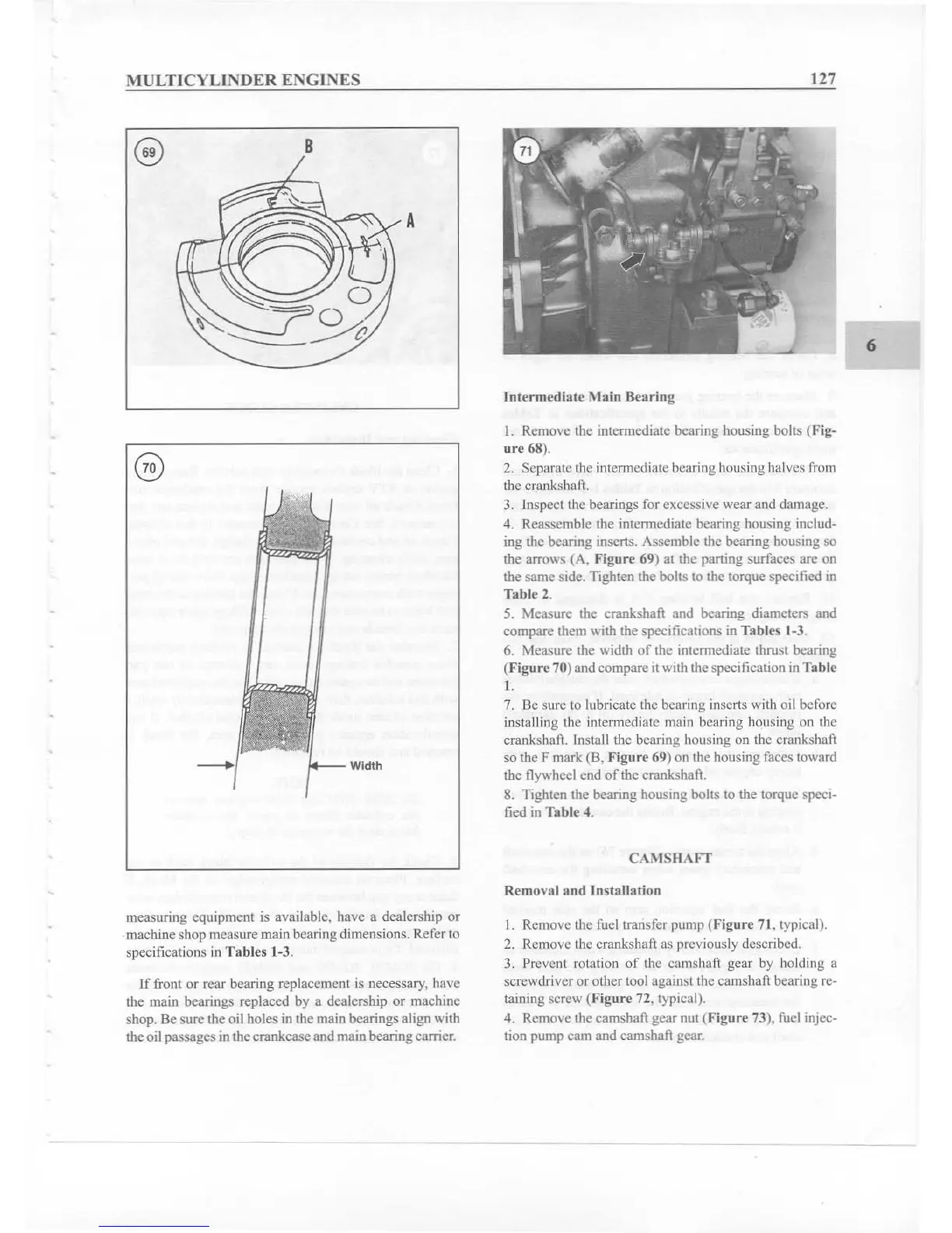
4. Reassemble the intermediate bearing housing includ-
ing the bearing inse
rt
s. Asse mble the bearing housing so
the arrows
(A.
Figure 69) at the parting surfaces are on
the same side.
Tighten the bolts to the torque specified in
Table 2.
5. Measure the crankshaft and bearing diameters and
compare them with the specifications in Tab les 1-3.
6. Measure the width
of
the intermediate thrust bearing
(Figure 70)and compare itwith the specification inTab le
I.
7. Be sure to lubricate the bearing inserts with oil before
installing the intermediate main bearing housing on the
crankshaft. Install the bearing housing on the crankshaft
so the F mark
(B, Fi
gur
e 69) on the housing faces toward
the flywheel end
of
the crankshaft.
8. Tighten the bearing housing bolts to the torque spcci-
fied in Table
4.
C":\
ISIiAfT
Removal
and
Installation
measuring equipment is available. have a dealership or
machine shop measure main bearing dimensions. R
ef
er to
specifications in Tables 1-3.
If
front or rear bearing rep lacement is necessary. have
the main bearings replaced by a dealership or machine
shop. Be sure the oil holes in the main bearings align with
the oil passages in the
cra
nkcase and mainbearing carrier.
I. Remove thc fuel transfer pump (Figure 71, typical).
2. Remove the crankshaft as previously described.
3. Prevent rotation
of
the camshaft gear by holding a
screwdriver or other tool against the camshaft bearing rc-
taining screw (Figure 72. typical).
4. Remove the camshaft gear nut
(Fi~
ure
73), fuel injec-
tion pump cam and camshaft gear.