128
5. Position the engine so the valve lifters will not fall out
when the camshaft is withdrawn.
6. Remove the bea ring retaining
screw (Figure 74), then
withdraw the camshaft.
7. Remove the valve lifters and mark them so they may
bereinstalled in their original locations.
NOTE
If
precision measuring equipment is not
avail
able, hOI
'1!
Step 8
pe
rformed by a
deal
-
ership or machine shop.
8. Check the bearing joumal(s) and lobes for signs
of
wear or sconng.
9. Measure the bearing joumal(s) and lobes (Figure 75)
and compare the results
10 the specifications in Tables
1-3. Replace the camshaft if the journal or lobes do not
meet
specifications.
10. Measure the stem diameter of the valve lifters and
compare it to the specification in T
ab
les 1-3. Measure the
lifter bores in the cylinder block. Calculate the lifter clear-
ance and compare it with the specification in Tables 1-3.
Replace the valve lifters if they do not meet spcciflca-
tions. Replace the valve lifter if the lifter face is scored,
galled, excessively worn or otherwise damaged.
II . Replace the ball bearing if it is damaged or feels
rough during rotation.
12. Installation is the reverse
of
removal. Note the fol-
lowing:
a. Ifinstallinga new camshaft. coat the camshaft lobes
with camshaft break-in lubricant. If reinstalling the
original camshaft, apply heavy oil to the camshaft
lobes.
b. Lubricate the camshaft bearing joumal(s) with
heavy engine oil before reinstallation.
c. Lightly tap the end
of
the camshaft to seat the ball
bearing in the engine. Rotate the camshaft to be
sure
it rotates freely.
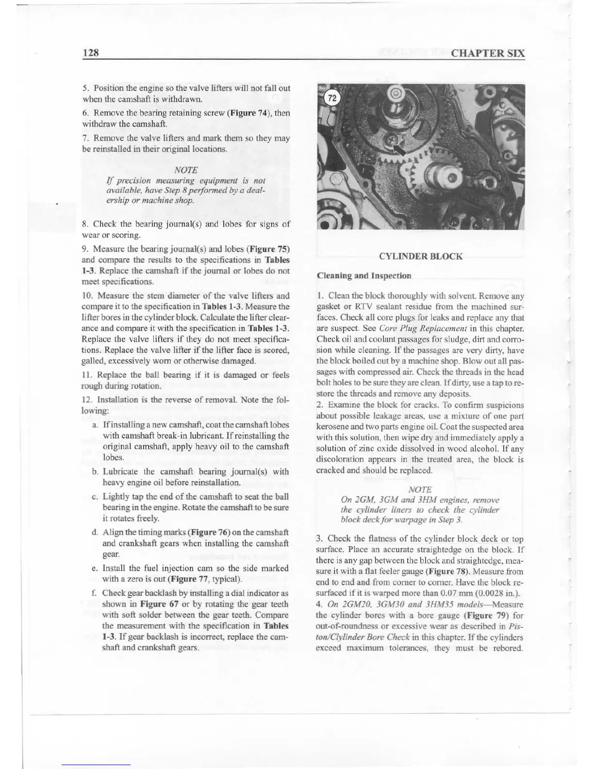
d. Align the timing marks
(Fi2ure 76) on the camshaft
and crankshaft gears when installing the camshaft
gear.
c. Install the fuel in
je
ction cam so the side marked
with a zero is out
(Fi
2ure
77, typical).
f.
Check gear backlash by installing a dial indicator as
she
....
-n in Fig
ur
e 67 or by rotating the gear teeth
with soft solder between the gear teeth. Compare
the measurement with the specification in
Tables
1-3. If gear backlash is incorrect. replace the cam-
shaft and crankshaft
gears.
CHAPT
ER SIX
CYLINDER
BLOCK
Cleaning
and
Inspection
I. Clean the block thoroughly with solvent. Remove any
gasket or RTV sealant residue from the machined sur-
faces. Check all core plugs for leaks and replace any that
arc suspect. See
Core Plug Replacement in this chapter.
Check oil and coolant passages for sludge, dirtand corro-
sion while cleaning. If the passages are very dirty, have
the block boiled out by a machine shop. Blowout all pas-
sages with compressed air. Check the threads in the head
bolt holesto
besure they are clean.
If
dirty, use a tap to
reo
store the threads and remove any deposits.
2. Examine the block for cracks. To confirm suspicions
about possible leakage areas, usc a mixture
of
one part
kerosene and two parts engine oil. Coat the
suspected area
with this solution. then wipe dry and immediately apply a
solution
of
zinc oxide dissolved in wood alcohol. If any
discoloration appears in the treated area, the block is
cracked and should be replaced,
NOTE
On 2GAf. 3GM and 3JfM engines, remm'e
the cylinder liners to check the cylinder
block deck/ or
warpage in Step 3.
3. Check the flatness
of
the cylinder block deck or top
surface. Place an accurate straightedge on the block.
If
there is any gap between the block and straightedge, rnea-
sure it with a flat feeler gauge
(Ffgure 78). Measure from
end to end and from comer to comer. Have the block re-
surfaced
i
fit
is warped more than 0.07 mm (0.0028 in.).
4. On 2GM20. 3GM30 and 3HM35 models- Measure
the cylinder bores with a bore gauge (f igure 79) for
out-of-roundness or excessive wear as described in
Pis-
ton/Clylinder Bore Check in this chapter. If the cylinders
exceed maximum tolerances. they must
be rebored.