130
Straig
htedge
block surface. When the cylinder head is installed, the
clamping force
of
the head against the liner protrusion se-
cures the liner in place. The protrusion also establishes a
gas-tight seal between the liner and the head gasket. In-
spectthe liners as follows:
NOTE
The liner isa
close
fi t in the block, but it may
be movable. Distortion or corrosion may
freeze the liner in the block, which will ne-
cess itate a
puller
to remove the liner:
Cylinder
lin
er
CHAPTE R SIX
Bore gauge
Prol
l1J
slon
~
~F-"
i
c;::
~
~ Cylinder block
~
E::
~
~
V
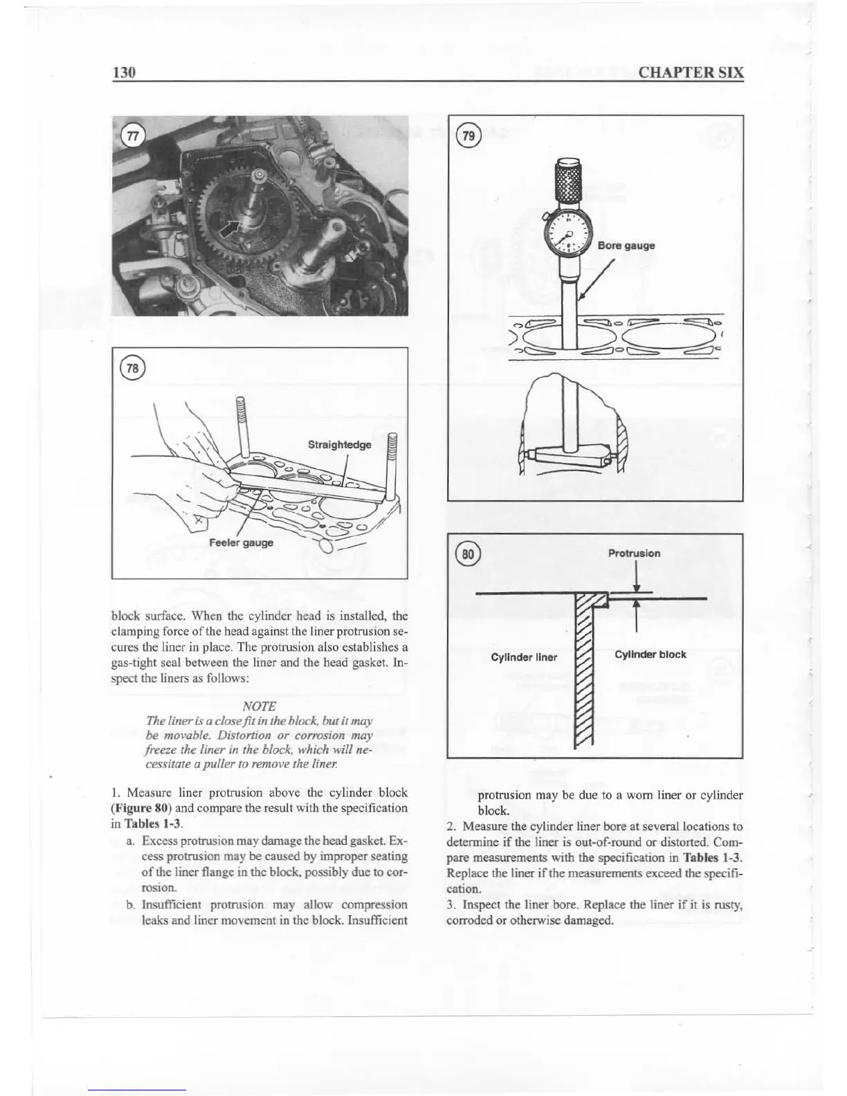
1. Measure liner protrusion above the cylinder block
(Figure SO)and compare the result with the specification
in Tab les 1-3.
a. Excess protrusion may damage the head gasket. Ex-
cess protrusion may
becaused by improper seating
of
the liner flange in the block. possibly due to cor-
rosion.
b. Insufficient protrusion may allow compression
leaks and liner movement in the block. Insufficient
protrusion may be due to a worn liner or cylinder
block.
2. Measure the cylinder liner bore at several locations to
determine
if
the liner is out
-of
-round or distorted. Com-
pare measurements with the
specification in Tables 1-3.
Replace the liner if the measurements exceed the
specifi-
cation.
3. Inspect the liner bore. Replace the liner if it is rusty.
corroded or otherwise damaged.