148
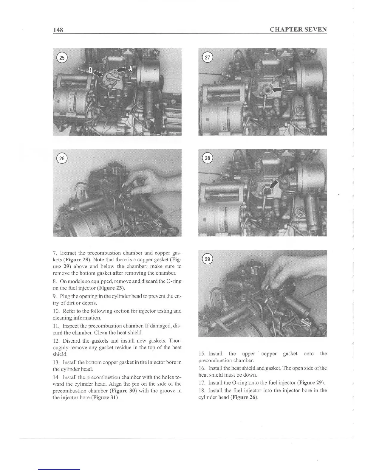
7. Extract the precombustion chamber and copper gas-
kets (Figure 28). Note that there is a copper gasket
(Fig-
ure
29) above and below the chamber; make sure to
remove the bottom gasket after remov ing the chamber.
8. On models so equipped, remove and discard the O-ring
on the fuel injector (Fig
ure
23).
9. Plug the opening in the cylinderhead to prevent the en-
try
of
dirt or debris.
10. Refer to the following section for injector testing and
cleaning information.
11. Inspect the precombustion chamber.
If
damaged, dis-
card the chamber. Clean the heat shield.
12. Discard the gaskets and install new gaskets. Thor-
oughly remove any gasket residue in the top of the heat
shield.
13. Install the bottomcoppergasket in the injector bore in
the cylinder head.
14, Install the precombustion chamber with the holes to-
ward the cylinder head. Align the pin on the side of the
precombustion chamber (Fig
ure
30) with the groove in
the injector bore (Figure 31).
CHAPTER
SEVEN
15. Install the upper copper gasket onto the
precombustion chamber.
16. Install the heat shield and gasket. The open side
of
the
heat shield must be down.
17. Install the O-ring onto the fuel injector (F
igur
e 29).
18, Install the fuel injector into the injector bore in the
cylinder head (Fig
ur
e 26).
,