152
seal properl y if reused. Always install new washers when
reconnecting a fitting.
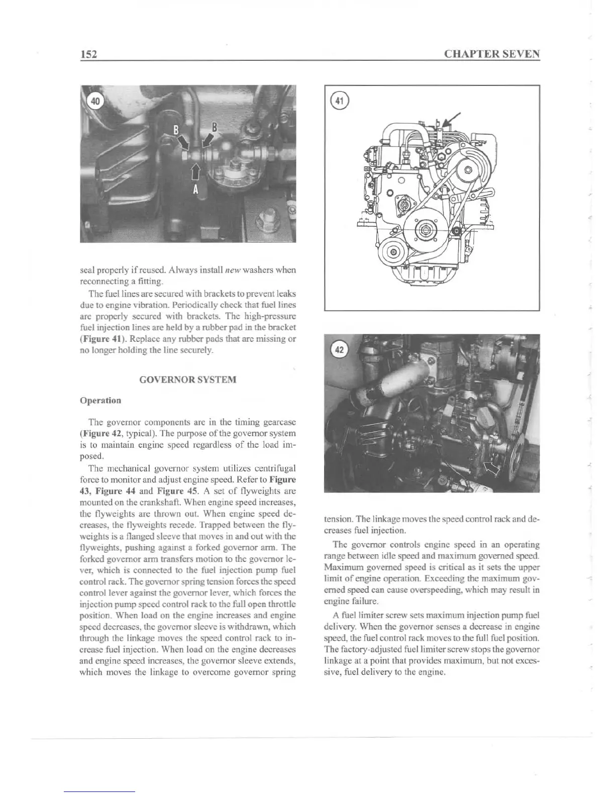
The fuel lines are secured with brackets to prevent leaks
due to
eng
ine vibration. Periodically check that fuel lines
are properly secured with brackets. The high-pressure
fuel injection lines are held by a rubber pad in the bracket
(Figure 41). Replace any rubber pads that are missing or
no longer holding the line securely.
GOVER:\OR
SYSTE:\I
Ope
rat
ion
The governor components are in the timing gearcasc
(Flgure 42, typical). The purpose of the governor system
is to maintain engine speed regardless
of
the load im-
posed.
The mechanical governor system utilizes centrifugal
force 10 monitor
and
adjust engine speed. Refer to Fi2u rc
43. Figure 44 and Figure 45. A set
of
flyweights are
mountcd on the crankshaft. When engine speed increases,
the flyweights are thrown out. When engine speed de-
creases, the flyweights
recede. Trapped between the fly-
weights is a flanged sleeve that moves in and out with the
flyweights, pushing against a forked governor arm. The
forked governor arm transfers motion to the governor le-
ver, which is connected to the fuel injection pump fuel
control rack. The governor spring tension forces the
speed
control lever against the governor lever, which forces the
injection pump
speed control rack to the full open throttle
position. When load on the engine increases and engine
speed decreases, the governor sleeve is withdrawn, which
through the linkage moves the speed control rack to in-
crease fuel injection. When load on the engine decreases
and engine
speed increases. the governor sleeve extends,
which moves the linkage to overcome governor spring
CHAPTER
SEVEN
tension. The linkage moves the speed controlrack and de-
creases fuel injection.
The governor controls engine speed in an operating
range between idle speed and maximum governed speed.
Maximum governed speed is critical as it sets the upper
limit
of
engine operation. Exceeding the maximum gov-
erned speed can cause overspceding, which may result in
engine failure.
A fuel limiter screw sets maximum injection pump fuel
delivery. When the governor senses a decrease in engine
speed, the fuel controlrack moves to the full fuelposition.
The factory-adjusted fucllimiter screw stops the governor
linkage at a point that provides maximum, but not exces-
sive, fuel delivery to the engine.