174
20. Install the cam (5,
Figure
24) and the cam retaining
screw (6).
NOTE
Replace the
pump
impeller anytime it is re-
movedfrom the pump.
If
the original impel-
ler must be reused, make sure to install
it
in
the same rotational direction as originally
installed.
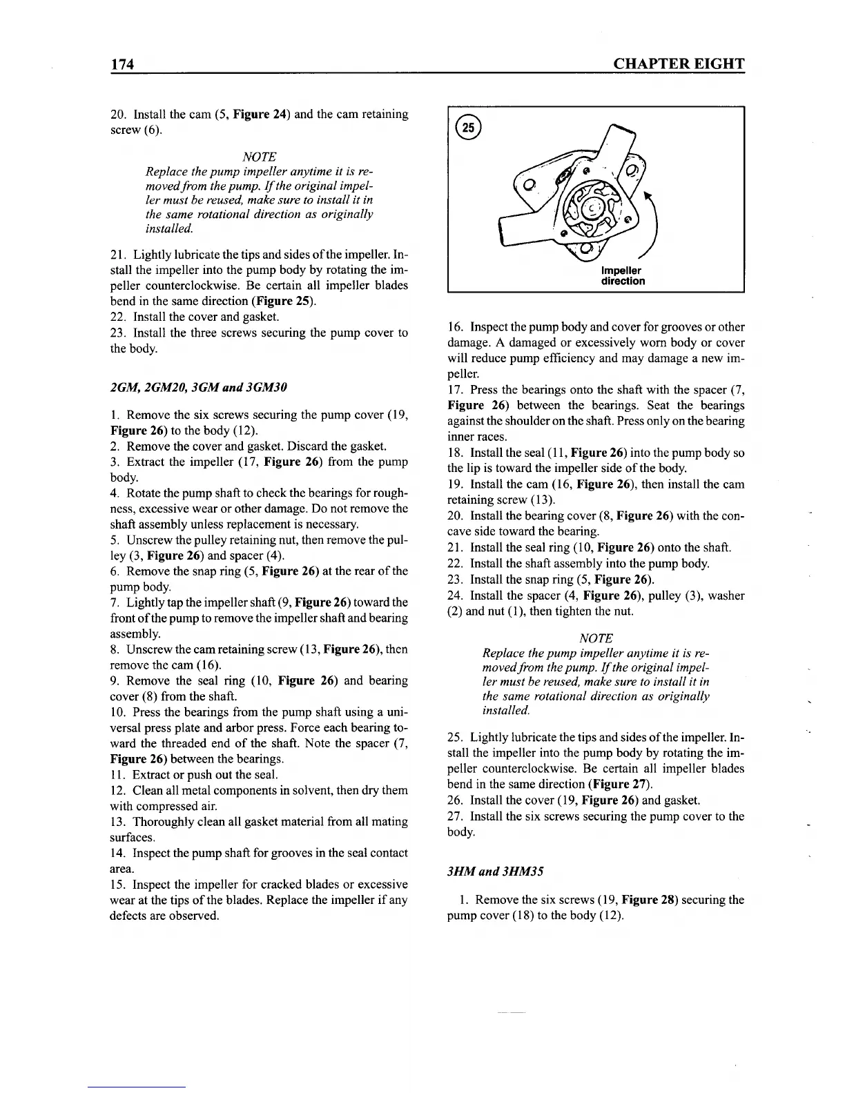
21. Lightly lubricate the tips and sides
of
the impeller. In-
stall the impeller into the pump body by rotating the im-
peller counterclockwise. Be certain all impeller blades
bend in the same direction (Figure 25).
22. Install the cover and gasket.
23. Install the three screws securing the pump cover to
the body.
2GM, 2GM20,
3GM
and
3GM30
1. Remove the six screws securing the pump cover (19,
Figure
26) to the body (12).
2. Remove the cover and gasket. Discard the gasket.
3. Extract the impeller (17,
Figure
26) from the pump
body.
4. Rotate the pump shaft to check the bearings for rough-
ness, excessive wear or other damage. Do not remove the
shaft assembly unless replacement is necessary.
5. Unscrew the pulley retaining nut, then remove the pul-
ley (3,
Figure
26) and spacer (4).
6. Remove the snap ring (5,
Figure
26) at the rear
of
the
pump body.
7. Lightly tap the impellershaft (9,
Figure
26) toward the
front
of
the pump to remove the impeller shaft and bearing
assembly.
8. Unscrew the cam retaining screw (13,
Figure
26), then
remove the cam (16).
9. Remove the seal ring (10,
Figure
26) and bearing
cover (8) from the shaft.
10. Press the bearings from the pump shaft using a uni-
versal press plate and arbor press. Force each bearing to-
ward the threaded end
of
the shaft. Note the spacer (7,
Figure
26) between the bearings.
11. Extract or push out the seal.
12. Clean all metal components in solvent, then dry them
with compressed air.
13. Thoroughly clean all gasket material from all mating
surfaces.
14. Inspect the pump shaft for grooves in the seal contact
area.
15. Inspect the impeller for cracked blades or excessive
wear at the tips
of
the blades. Replace the impeller if any
defects are observed.
CHAPTER
EIGHT
Impeller
direction
16. Inspect the pump body and cover for grooves or other
damage. A damaged or excessively worn body or cover
will reduce pump efficiency and may damage a new im-
peller.
17. Press the bearings onto the shaft with the spacer (7,
Figure
26) between the bearings. Seat the bearings
against the shoulder on the shaft. Press only on the bearing
mnerraces.
18. Install the seal (11,
Figure
26) into the pump body so
the lip is toward the impeller side
of
the body.
19. Install the cam (16,
Figure
26), then install the cam
retaining screw (13).
20. Install the bearing cover (8,
Figure
26) with the con-
cave side toward the bearing.
21. Install the seal ring (10,
Figure
26) onto the shaft.
22. Install the shaft assembly into the pump body.
23. Install the snap ring (5,
Figure
26).
24. Install the spacer (4,
Figure
26), pulley (3), washer
(2) and nut (1), then tighten the nut.
NOTE
Replace the
pump
impeller anytime
it
is re-
movedfrom the pump.
If
the original impel-
ler must be reused, make sure to install it in
the same rotational direction as originally
installed.
25. Lightly lubricate the tips and sides
of
the impeller. In-
stall the impeller into the pump body by rotating the im-
peller counterclockwise. Be certain all impeller blades
bend in the same direction (Figure 27).
26. Install the cover (19,
Figure
26) and gasket.
27. Install the six screws securing the pump cover to the
body.
3HM
and
3HM35
1. Remove the six screws (19,
Figure
28) securing the
pump cover (18) to the body (12).