TRANSMISSION
KMSERIES
207
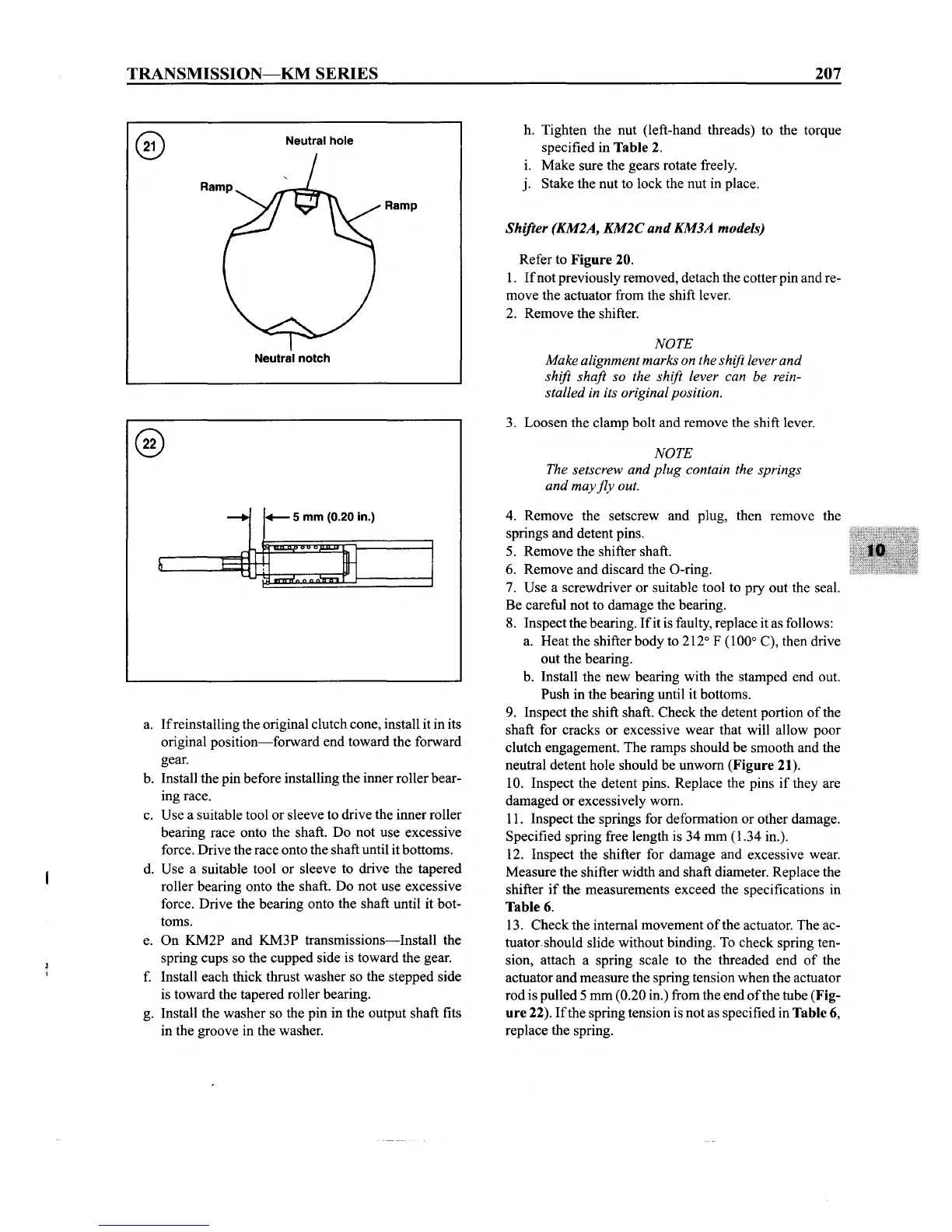
Neutral hole
Neutral
notch
Ramp
h. Tighten the nut (left-hand threads) to the torque
specified in Table 2.
1. Make sure the gears rotate freely.
j. Stake the nut to lock the nut in place.
Shifter (KM2A,
KM2C
and
KM3A models)
Refer to Figure 20.
1.
If
not previously removed, detach the cotter pin and re-
move the actuator from the shift lever.
2. Remove the shifter.
NOTE
Make alignment marks on the shift lever and
shift shaft so the shift lever can be rein-
stalled in its original position.
3. Loosen the clamp bolt and remove the shift lever.
NOTE
The setscrew and
plug
contain the springs
and may
fly
out.
a. Ifreinstalling the original clutch cone, install it in its
original
position-forward
end toward the forward
gear.
b. Install the pin before installing the inner roller bear-
ing race.
c. Use a suitable tool or sleeve to drive the inner roller
bearing race onto the shaft. Do not use excessive
force. Drive the race onto the shaft until itbottoms.
d. Use a suitable tool or sleeve to drive the tapered
roller bearing onto the shaft. Do not use excessive
force. Drive the bearing onto the shaft until it bot-
toms.
e. On KM2P and KM3P transmissions-Install the
spring cups so the cupped side is toward the gear.
f. Install each thick thrust washer so the stepped side
is toward the tapered roller bearing.
g. Install the washer so the pin in the output shaft fits
in the groove in the washer.
4. Remove the setscrew and plug, then remove the
springs and detent pins.
5. Remove the shifter shaft.
6. Remove and discard the O-ring.
7. Use a screwdriver or suitable tool to pry out the seal.
Be careful not to damage the bearing.
8. Inspect the bearing.
Ifit
is faulty,replace it as follows:
a. Heat the shifter body to 212
0
F
(l00°
C), then drive
out the bearing.
b. Install the new bearing with the stamped end out.
Push in the bearing until it bottoms.
9. Inspect the shift shaft. Check the detent portion
of
the
shaft for cracks or excessive wear that will allow poor
clutch engagement. The ramps should be smooth and the
neutral detent hole should be unworn (Figure
21).
10. Inspect the detent pins. Replace the pins if they are
damaged or excessively worn.
11. Inspect the springs for deformation or other damage.
Specified spring free length is 34 mm (1.34 in.).
12. Inspect the shifter for damage and excessive wear.
Measure the shifter width and shaft diameter. Replace the
shifter if the measurements exceed the specifications in
Table 6.
13. Check the internal movement
of
the actuator. The ac-
tuatorshould slide without binding. To check spring ten-
sion, attach a spring scale to the threaded end
of
the
actuator and measure the spring tension when the actuator
rod is pulled 5 mm
(0.20 in.) from the end
of
the tube (Fig-
ure
22).
If
the spring tension is not as specified in Table 6,
replace the spring.