212
1. Install the input shaft assembly in the transmission
case.
2. Position the
transmissi~n
case so the open end is up.
3. Install the outer bearing race on the input shaft tapered
bearing.
4. Measure the distance (A, Figure 30) in millimeters
from the mounting flange mating surface on the case to
the top
of
the bearing race. Record the measurement.
5. Measure the distance (B, Figure 31) from the mount-
ing flange mating surface to the bottom
ofthe
bearing race
bore for the input shaft bearing.
6. Subtract the A measurement from the B measurement.
7. From the result obtained in Step 6, subtract 0.0-0.05
mm. This result equals the thickness
of
the shim(s) that
must be installed in the bearing bore in the mounting
flange.
8. Install the shim(s) in the bearing bore in the mounting
flange, then press the bearing outerrace into the mounting
flange on top
of
the shims. Be sure the race is bottomed.
Output
Shaft
In the following procedure to adjust bearing preload,
the neutral position
of
the clutch cone must be established
for proper transmission operation. The desired clutch
cone groove centerline on Model KM2P is 48.3 mm from
the mating surface
of
the transmission case. On Model
KM3P the desired clutch groove centerline is 47.3 mm
from the mating surface
of
the transmission case.
NOTE
To perform the following bearing adjust-
ment procedure, the output shaft must be out
of
the case and the outer bearing races must
be on the bearings and not installed in the
case or mountingflange.
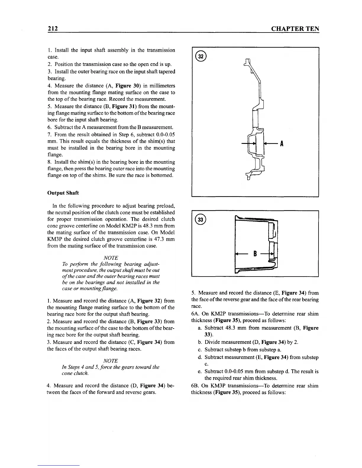
1. Measure and record the distance (A, Figure 32) from
the mounting flange mating surface to the bottom
of
the
bearing race bore for the output shaft bearing.
2. Measure and record the distance (B, Figure 33) from
the mounting surface
of
the case to the bottom
ofthe
bear-
ing race bore for the output shaft bearing.
3. Measure and record the distance (C, Figure 34) from
the faces
of
the output shaft bearing races.
NOTE
In Steps
4 and 5,force the gears toward the
cone clutch.
4. Measure and record the distance (D, Figure 34) be-
tween the faces
of
the forward and reverse gears.
CHAPTER
TEN
B
5. Measure and record the distance (E, Figure 34) from
the face
ofthe
reverse gear and the face
ofthe
rear bearing
race.
6A. On KM2P
transmissions-To
determine rear shim
thickness (Figure 35), proceed as follows:
a. Subtract 48.3 mm from measurement (B, Figure
33).
b. Divide measurement (D, Figure 34) by 2.
c. Subtract substep b from substep a.
d. Subtract measurement (E, Figure 34) from substep
c.
e. Subtract 0.0-0.05 mm from substep d. The result is
the required rear shim thickness.
6B. On KM3P
transmissions-To
determine rear shim
thickness (Figure 35), proceed as follows: