OPERATION, LUBRICATION, MAINTENANCE AND TUNE-UP
59
@
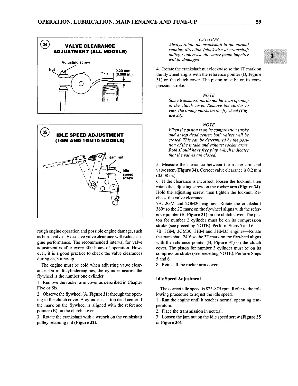
VALVE
CLEARANCE
ADJUSTMENT
(ALL
MODELS)
Adjusting screw
CAUTION
Always rotate the crankshaft in the normal
running direction (clockwise at crankshaft
pulley); otherwise the water
pump
impeller
will be damaged.
4. Rotate the crankshaft nut clockwise so the 1T mark on
the flywheel aligns with the reference pointer (B,
Figure
31) on the clutch cover. The piston must be on its com-
pression stroke.
NOTE
Some transmissions do not have an opening
in the clutch cover. Remove the starter to
view the timing marks on the flywheel (Fig-
ure 33).
IDLE
SPEED
ADJUSTMENT
(1GM
AND
1GM10
MODELS)
rough engine operation and possible engine damage, such
as burnt valves. Excessive valve clearance will reduce en-
gine performance. The recommended interval for valve
adjustment is after every 300 hours
of
operation. How-
ever, it is a good practice to check the valve clearances
during each tune-up.
The engine must be cold when adjusting valve clear-
ance. On multicylinderengines, the cylinder nearest the
flywheel is the number one cylinder.
1. Remove the rocker arm cover as described in Chapter
Five or Six.
2. Observe the flywheel (A,
Figure
31) through the open-
ing in the clutch cover. A cylinder is at top dead center
if
the mark on the flywheel is aligned with the reference
pointer (B) on the clutch cover.
3. Rotate the crankshaft with a wrench on the crankshaft
pulley retaining nut
(Figure
32).
..
,""\-"~'
,.....-
..
-<:
j-
..-
l ..
'--"~
Idle
speed
screw
NOTE
When thepiston is on its compression stroke
and
at top dead center, both valves will be
closed. This can be determined by the posi-
tion
of
the intake
and
exhaust rocker arms.
Both should have free play, which indicates
that the valves are closed.
5. Measure the clearance between the rocker arm and
valve stem
(Figure
34). Correct valve clearance is 0.2 mm
(0.008 in.).
6.
If
the clearance is incorrect, loosen the locknut, then
rotate the adjusting screw on the rocker arm
(Figure
34).
Hold the adjusting screw, then tighten the locknut. Re-
check the valve clearance.
7A. 2GM and 2GM20
engines-Rotate
the crankshaft
360
0
so the 2T mark on the flywheel aligns with the refer-
ence pointer (B,
Figure
31) on the clutch cover. The pis-
ton for number 2 cylinder must be on its compression
stroke (see preceding NOTE). Perform Steps 5 and 6.
7B. 3GM, 3GM30, 3HM and 3HM35
engines-Rotate
the crankshaft 240
0
so the 3T mark on the flywheel aligns
with the reference pointer (B,
Figure
31) on the clutch
cover. The piston for number 3 cylinder must be on its
compression stroke (see preceding NOTE). Perform Steps
5 and 6.
8. Reinstall the rocker arm cover.
Idle
Speed
Adjustment
The correct idle speed is 825-875 rpm. Refer to the fol-
lowing procedure to adjust the idle speed.
1. Run the engine until it reaches normal operating tem-
perature.
2. Place the transmission in neutral.
3. Loosen the
jam
nut on the idle speed screw
(Figure
35
or
Figure
36).