88
CHAPTER
FIVE
/
/
/
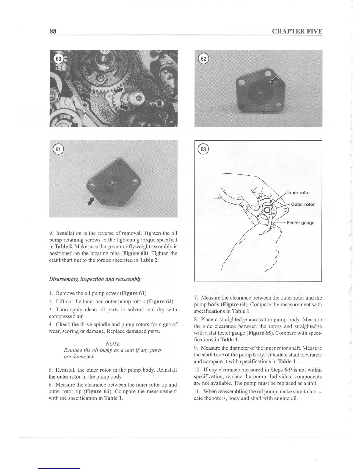
Outer rotor
Inner
rotor
/ J
~
;;~:J-k';:-
-
Feeler gauge
9. Installation is the reverse
of
removal. Tighten the oil
pump retaining screws to the tightening torque specified
in Tabl e 2. Make sure the governor flyweight assembly is
positioned on the locating pins
(Figure
60). Tighten the
crankshaft nut to the torque specified in Table 2.
Disassembly, inspection
and
reassembly
1. Remove the oil pump cover
(Fig
ure
61).
2. Lift out the inner and outer pump rotors (F
igure
62).
3. Thoroughly clean all parts in solvent and dry with
compressed air.
4. Check the drive spindle and pump
rotors for signs
of
wear, scoring or damage. Replace damaged parts.
NOTE
Replace the oil
pump
as a unit
if
any parts
are damaged.
5. Reinstall the inner rotor in the pump body. Reinstall
the outer rotor in the pump body.
6. Measure the clearance between the inner
rotor tip and
outer rotor tip
(Figure
63). Compare the measurement
with the specification in
Tab
le 1.
7. Measure the clearance between the outer rotor and the
pump body
(Figur
e 64). Compare the measurement with
specifications in
Table I.
8. Place a straightedge across the pump body. Measure
the side clearance between the rotors and straightedge
with a flat feeler gauge (Fig
ure
65). Compare with speci-
fications in Table
I.
9. Measure the diameter
of
the inner rotor shaft. Measure
the shaft bore
of
the pump body. Calculate shaft clearance
and compare it with specifications in
Tab
le 1.
10. If any clearance measured in Steps 6-9 is not within
specification, replace the pump. Individual components
are not available. The pump must be replaced as a unit.
11
. When reassembling the oil pump, make sure to lubri-
cate the rotors, body and shaft with engine oil.