76
2. Recheck all oil and water passages for cleanliness.
3. Apply Three Bond 50 gasket scaler to both sides
of
a
new cylinder head gasket.
~
4. Place the new head gasket over the cylinder head studs
on the block. Make sure the TOP mark (Figure 20) on the
gasket is up.
5. Carefully lower the head onto the cylinder block.
6. Apply engine oil to the threads on the cylinder head
studs .
7. Install and tighten the cylinder head retaining nuts fin-
ger-tight.
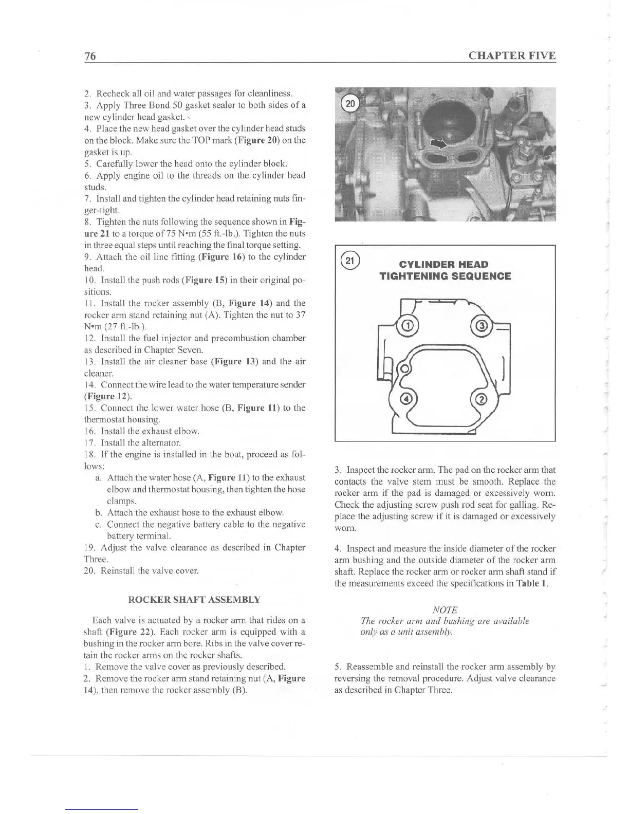
8. Tighten the nuts following the sequence shown in Fig-
ure
21 to a torque
of75
Nom(55 ft.-lb.). Tighten the nuts
in three equal steps until reach ing the final torgue setting.
9. Attach the oil line fitting (Figure 16) to the cylinder
head.
10. Install the push rods (Figure 15) in their original po-
sitions .
11. Install the rocker assembly
(13,
f ig
ur
e 14) and the
rocker arm stand retaining nut (A). Tighten the nut to 37
Nom (27 ft.-lb.).
12. Install the fuel injector and precombustion chamber
as described in Chapter Seven.
13. Install the air cleaner base (Ffgure
13) and the air
cleaner.
14. Connect the wire lead to the water temperature sender
(Ffgure 12).
15. Connect the lower water hose (B,
Figure
11) to the
thermostat housing.
16. Install the exhaust elbow.
17. Install the alternator.
IS.
If
the engine is installed in the boat, proceed as fol-
lows:
a. Attach the water hose (A, Figure II ) to the exhaust
elbow and thermostathousing, then tighten the hose
clamps.
b. Attach the exhaust hose to the exhaust elbow.
e. Connect the negative battery cable to
the negative
battery term inal.
19. Adjust the valve clearance as described in Chapter
Three.
20. Reinstall the valve
cover.
ROCK
ER
SHAFT
ASS
EMBLY
Each valve is actuated by a rocker arm that rides on a
shaft (Figure 22). Each rocker arm is equipped with a
bushing in the rocker
ann
bore. Ribs in the valve cover re-
tain the rocker arms on the rocker shafts.
1. Remove the valve cover as previously described.
2. Remove the rocker arm stand retain ing nut (A, F
igure
14), then remove the rocker assembly (B).
CHAPTER FIVE
CYLINDER
HEAD
TIGHTENING
SEQUENCE
3. Inspect the rocker arm. The pad on the rocker arm that
contacts the valve stem must
be smooth. Replace the
rocker artu if the pad is damaged or excessively worn .
Check
the ad
ju
sting screw push rod seat for galling. Re-
place the adjusting screw
if
it is damaged or excess ively
worn.
4. Inspect and meas
ur
e the inside diameter of the rocker
arm bushing and the outside diameter
of
the rocker arm
shaft. Replace the rocker arm or rocker arm shaft stand if
the measurements exceed the specifications in Table
1.
NOTE
The rocker arm and bushing are available
only as a uni t assembly.
5. Reasse mble and reinstall the rocker arm assembly by
reversing the removal procedure. Adjust valve clearance
as described in Chapter Three.