Chapter
3
Fuel Injection Equipment
2. Disassembly, Reassembly and
Inspection
of Governor
4LHA Series
(7) Put the governor lever shaft
assembly
in the
governor
case,
insert the governor lever shaft
until
the O-ring groove protrudes
from
out the opposite
side
of the governor
case,
and fit the O-ring.
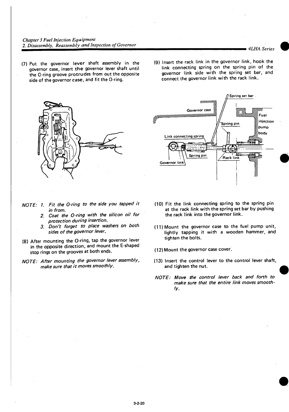
(9)
Insert
the rack
link
in the governor link, hook the
link
connecting spring on the spring pin of the
governor
link
side
with
the spring set bar, and
connect
the governor
link
with
the rack link.
Spring
set bar
NOTE: 1. Fit the O-ring to the side you tapped it
in from.
2. Coat the O-ring with the silicon oil for
protection during insertion.
3. Don't forget to place washers on both
sides of the governor lever.
(8) After mounting the O-ring, tap the governor lever
in the opposite direction, and mount the
E-shaped
stop rings on the grooves at
both
ends.
NOTE: After mounting the governor lever assembly,
make sure that it moves smoothly.
(10) Fit the
link
connecting spring to the spring pin
at the rack
link
with
the spring set bar by pushing
the rack
link
into
the governor link.
(11) Mount the governor
case
to the fuel pump
unit,
lightly
tapping it
with
a wooden hammer, and
tighten
the bolts.
(12) Mount the governor
case
cover.
(13)
Insert
the control lever to the control lever shaft,
and
tighten
the nut.
NOTE: Move the control lever back and forth to
make sure that the entire link moves smooth-
ly.
3-2-20
 Loading...


