2
filter intensity;
• With self-checking for input/output hardware
configuration and error code display function;
• With RS232 output(standard)or RS422 output
(optional),communicating with PC by continuously send mode
or command mode;
• With 20mA current loop output for connection of
scoreboard;
• With 4~20mA analog output(optional);
• With 6 inputs and 7 relay outputs to control max.
2 materials;
1.3 Connecting to Other Devices
1
1.3.1 Connection to load cell
Connect this indicator to load cell through the 9-pin load cell
connector located at the back. Refer to the below table for
load cell pin assignment.
① ② ③ ④ ⑤
⑥ ⑦ ⑧ ⑨
1
Turn scale off and cut off power before making any connections or disconnections.
Short connect PIN 1 AND PIN 2, PIN 6 and PIN 7 when connected
to load cell with a 4-wire cable;
CAUTION
• Connection between load cell and indicator must be reliable;
shield-wire must be connected to ground reliably;
• Load cell and indicator are all
static-electricity-sensitive devices,measures must be
taken to ensure safety.
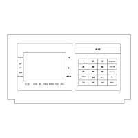
1.3.2 Connection to PC or SCOREBOARD or current display
(optional)
From the 15-pin interface located at the back, you could
• Connect indicator to computer via RS232 output or
RS422 output (optional);
• Connect indictor to scoreboard via 20mA current
loop output;
• Connect indicator to current display with 4~20mA
analog output.
.
15-pin connector
PIN # ASSIGNMENT
1 E-
2 S-
5 SHIELD
6 E+
7 S+
8 IN-
9 IN+
 Loading...