3
• Connect indicator to computer via RS232 output or
RS422 output (optional);
Data format for RS232 or RS422 is the same. Data is transmitted
in ASCII code. Data format is as listed below(one group):
1 2 3 4 5 6 7 8 9 10
START DATA STOP
There are two modes to communicate with PC:
• Continuously send, and
• Command mode.
A. Continuously send
Data transmitted is tare weight or net weight from the display
of the indicator. Each time it sends one frame data to pc, one
frame consists of 9 groups while the data format of one group
is as listed above. Below is the content for one frame:
For example,
Now the indicator displays 50.00KG, then the frame indicator
sends to PC is : =+0050.00;
If the indicator displays -0.040KG, then the frame indicator
sends to PC is : =-000.040;
B. Command mode
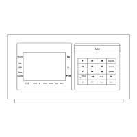
PIN # ASSIGNMENT PIN # ASSIGNMENT
1 RS422 OUTPUT+ 9 SCOREBOARD OUT+
2 RS422 OUTPUT- 10 SCOREBOARD OUT-
3 RS422 IN- 12 4~20mA I-
4 RS422 IN+ 13 4~20mA I+
6 RS232 RXD 14 CALIBRATION+
7 RS232 TXD 15 CALIBRATION-
8 GND
Note1: RS422 output is optional;
Note2: Function of short-connect pin 14 and pin 15 is as what
the calibration head performs.
Calibration head is a 15-pin connector with pin
14 and pin 15
hort connected which is usually packed together
with the manual.
ROUP
NO.
CONTENT NOTES
1
=
START SIGNAL
2
+ OR -
SIGN SINAL
3 High digit
4 :
5 :
6 If decimal point is 3, then this group is “.”
7 If decimal point is 2, then this group is “.”
8 If decimal point is 1, then this group is “.”
9
WEIGHING
DATA
Low digit
 Loading...