28 29
INSTALLATION GUIDEINSTALLATION GUIDE
If the boundary wire is required to protect a ower bed or other obstacle within the Working
area then please follow this suggestion. The boundary wire should be laid from the main
Boundary in a straight line as shown then around the prole of the obstacle and then back
to the main boundary again, the gap between the two boundary wires shown should be
as close as possible without crossing. The same peg can be used to x them; the YARD
FORCE Robotic Lawnmower will mow freely over the double wire.
If you nd you do not have enough Boundary wire left to go around the whole area you
wish to protect exclude from cutting or if you need to make some changes later then
spare wire can be purchased and it is easy to connect with the provided Boundary wire
connectors ( Item 18).
4.5. Prepare the boundary Wire For the Charging Station
After laying the boundary wire you need a decrustation pliers (See below left photo) or
scissor to clear the teon cover of the wire and explode the metal threads for connection
to the charging station. A length of 10 - 15 mm metal exploring metal threads are
recommended. You may twist the end of the metal threads with your ngers to make it
tight for connection.
Leaving about 1meter extra wire, peg the wire along the boundary from the rear side of the
charging station with a distance of the pegs of 80cm. When you nish the layout and back
to the charging station, leave another 1meter extra wire and then cut it.
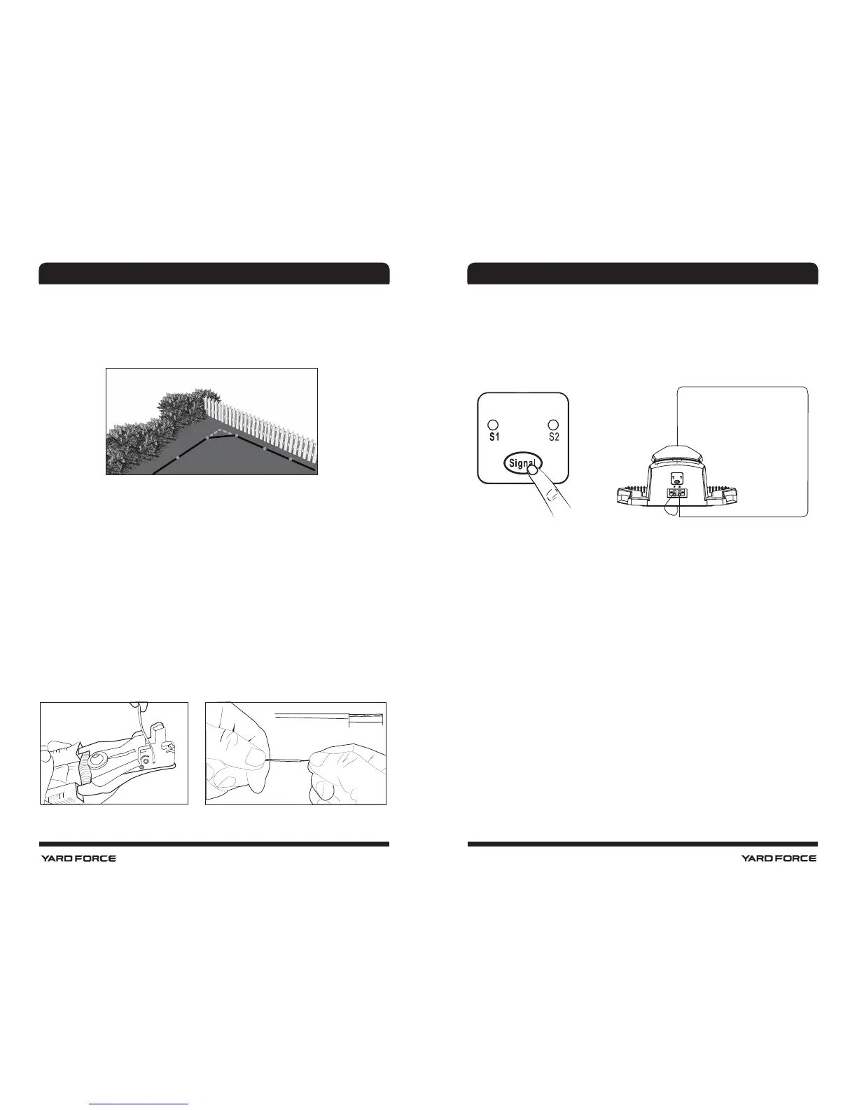
Make sure if a square corner is uncounted in your working zone, please do not create
a 90deg sharp corner as below, the Mower will turn here anyway and cut this area as it
turns, so best leave a 45deg angle in each corner see below.
NO
OK
10 - 15 mm
4.6. Connect the Charging Station With the Boundary Wire
Onceconnectorshavebeenpreparedtoeachofthetwoboundarywireendsthenthese
canbe connectedtothechargingstationasshownbelow.Itisimportanttolaythewire
from thefrontof thechargingstationunderneaththebasetoprotectitbeforeconnecting
at the rear.Thisconnector shouldthenbeconnectedtotheLefthandtabmarked"F",and
the rearboundarywire connectorisconnectedtotheRighthandtabmarked"B".
IMPORTANT INFORMATION
Double check that the charger connections are as shown below. Even if it is blue light the
connectors are wrongly connected the machine will not work.
NOTE !
When the working area is less than 100 m
2
or total boundary wire less than
40 m, please connect a 10 Ω / 20 W cement resistance to the boundary wire, or contact
the service.
After connecting the “F” and "B" connectors to the charging station, the charging station
can be xed down with the boundary pegs(item 15). Please ensure before this is done that
the charging station is still situated on a at surface and mains connection is still can be
reached. Also ensure that 2m of straight boundary wire is in front and 1 m to rear of station
and any surplus boundary cable is tucked under the charging station base to protect it.
Once this is done, Connect the charger extension cable (Item 14) to Charging base,
meanwhile ensuring that the power supply is not connected to mains voltage just yet.
Once these connections are made, plug in power supply, there is a blue LED Light on
Connector F
Connector B