16 support@yardistrystructures.com
Avery Inst 4 - Frame Assembly
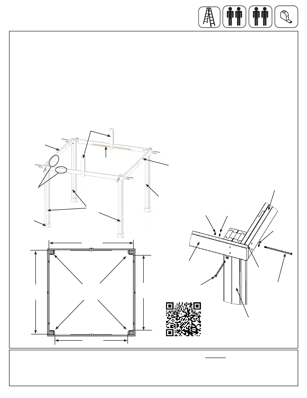
A: Move your Post Assemblies to the nal location. Make sure the ground is at and level before continuing
assembly.
B: With one person at each Post stand two complete Post Assemblies. A third person places one Beam
Assembly - Side against the outside of each Post, ush to the tops and outside corners. Notice bolt hole
orientation on the assemblies. A fourth person attaches Beam to Post with one 3/8 x 9-1/2” Hex Bolt (with two
3/8” at washers and one 3/8” lock nut) per Post. The distance from the outside of one Post to the outside of the
second Post should be 10’ 2-1/4”. (g. 5.1, 5.2 and 5.3)
C: Place one Beam Assembly - Front/Back against two Post Assemblies so the (405) Cross Gusset Support faces
the inside and is ush to the top and outside corner of Beam Assembly - Side, then attach with one 3/8 x 8” Hex
Bolt (with two 3/8” at washers and one 3/8” lock nut) per Post, The distance from the outside of one Post to the
outside of the second Post should be 10’ 6”. (g. 5.1 and 5.2) See g. 5.3 for accurate positioning of Posts.
Avery Inst 4 - Frame Assembly
Step 5: Frame Assembly and Anchoring
Part 1
Fig. 5.1
Fig. 5.2
Hardware
4 x 3/8 x 9-1/2” Hex Bolt (3/8” at washer x 2, 3/8” lock nut)
4 x 3/8 x 8” Hex Bolt (3/8” at washer x 2, 3/8” lock nut)
Note hole
orientation (on
bottom)
Fig. 5.3
3/8” Lock
Nut
3/8” Flat
Washer
3/8” Flat
Washer
3/8 x 8”
Hex Bolt
3/8 x 9-1/2”
Hex Bolt
Beam
Assembly -
Side
Post Assembly
Post
Assembly
(405) Cross
Gusset Support
Post
Assembly
Plinth
Beam Assembly
- Front/Back
Beam
Assembly -
Side
Beam Assembly -
Front/Back
Beam Assembly
- Side
post to post
plinth to plinth
"
3
9'-
4
"
3
2
1
3
'
-2
1
9
"
3
2
1
3'
-
2
1
9
"
1
"
2
9'-4
10'-2
1
4
10'-6"
9’ 3/4”
Plinth to Plinth
Plinth to Plinth
13’ 2-5/8”
Post to Post
10’ 2-1/4”
Post to Post
9’ 4-1/2”
10’ 6”
Post to Post
D: Repeat Steps B and C for remaining
Beam Assemblies. See g. 5.3 for
accurate positioning of Posts.
Flush
x 3
http://bit.ly/avery5-6