2.
3.
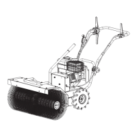
Remove the cable clips, clipped on the upper handle, and
secure all loose cables against the handle bar with the clips
to prevent cable damage. (See
Figure 3c
)
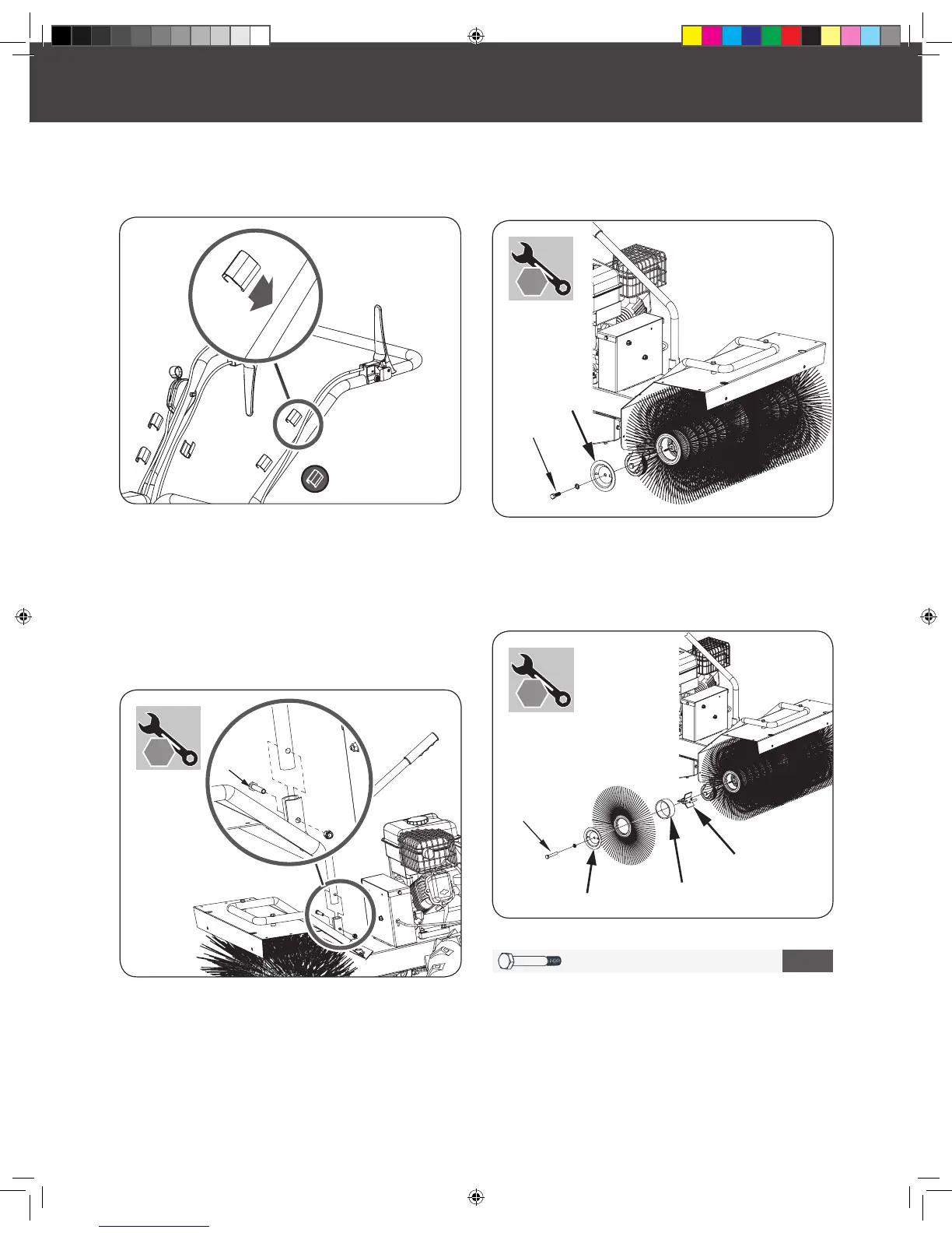
3.
M10 X 70 X 2
2
Using the hardware kit packet #2, attach the extension shaft,
bushing and brush using the M10x70 bolt. Reattach the
Brush Guard onto the end of the sweeper head assembly. (See
Figure 5b
)
Repeat this assembly process for the other side.
Figure 4
Figure 5a
Figure 5b
Figure 3c
X 2
BRUSH DIRECTION CONTROL LEVER
BRUSH EXTENSION
Remove the bolt M8x45 and nut M8 from the mounting
bracket. (See
Figure 4
)
Insert and align the brush direction control lever into the
mounting bracket. Attach the brush direction control lever
into the bracket by using bolt M8x45 and nut M8.
Loosen bolt M10x30 and remove this bolt, washer 10 and
brush guard. (See
Figure 5a
).
1.
1.
2.