9 CDBR Braking Unit and LKEB Braking Resistor Selection
YASKAWA ELECTRIC TOBP C720600 01E YASKAWA AC Drive Option CDBR-D, LKEB- Installation Manual 65
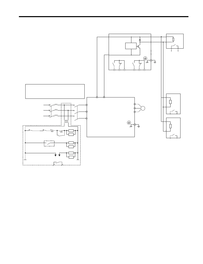
Figure 31
Figure 31 Fault Circuit Connection Diagram D
(CDBR Braking Unit and LKEB Braking Resistor Unit in Parallel)
<1> 200 V class drives do not require a control circuit transformer.
<2> Set L3-04 to 0 or 3 to disable Stall Prevention during deceleration when using an LKEB Braking Resistor Unit.
Enabling the function under these conditions may prevent the drive from stopping within the specified
deceleration time.
<3> Wire the thermal relay trip contacts in parallel when connecting multiple LKEB Braking Resistor units.
P
B
12
12
P
B
MA MB MC EA EB EC
<2>
ELCB (MCCB)
R
T
S
MC
R/L1
S/L2
T/L3
M
U/T
1
V/T2
W/T3
ON
OFF
THRX
SA
1
2
TRX
MC
MA
MC
TRX
MC
SA
SA
THRX
MC MB
<1>
B1
B2
B
P
12
SC
SB
Braking resistor
overheat switch
(thermal relay trip)
CDBR transistor
short-circuit
detection output
250 Vac, max.1 A
30 Vdc, max.1 A
min.5 Vdc, 10 mA
(to customer circuit)
Fault output
250 Vac, max.1 A
30 Vdc, max.1 A
min.5 Vdc, 10 mA
(to customer circuit)
Level
Sensor
CDBR Braking Unit
LKEB Braking
Resistor Unit
3-phase
Drive
Wiring sequence should shut off power to the drive
when a CDBR transistor short-circuit detection
output is triggered or a braking resistor unit
overheat switch is triggered.
Fault relay contact
Braking resistor
overheat switch
(thermal relay trip)
(Ground)
<3>
<3>
+
-
+3
-
TOBP_C720600_01E_9_0_E.book 65 ページ 2017年8月25日 金曜日 午後2時8分